Physical Address
304 North Cardinal St.
Dorchester Center, MA 02124
Physical Address
304 North Cardinal St.
Dorchester Center, MA 02124
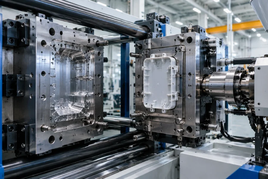
Injection molding cycle time is the time required to complete one machine cycle, from the beginning of one cycle to the beginning of the next. It determines theoretical production capacity and contributes directly to machine cost per part.
The main cycle-time variables are filling and holding time, cooling requirements, screw recovery, and mold movements. Optimizing them requires identifying the operation that limits the actual machine cycle while maintaining dimensional accuracy, surface quality, and reliable ejection.
One molding cycle can produce one or multiple parts, depending on the number of active mold cavities. The cycle includes three main categories.
These operations can overlap. Cooling starts when molten plastic contacts the mold, while screw recovery may occur during the remaining cooling period. Adding every operation’s duration without accounting for overlap can overestimate the actual machine cycle.
Three cooling-related terms should be distinguished when calculating cycle time.
| Term | Meaning |
|---|---|
| Physical cooling | Heat loss that begins when molten plastic contacts the mold and continues after ejection. |
| Programmed cooling time | The cooling interval specified in the machine control sequence. Its start point depends on the machine settings. |
| Additional cooling after holding | The remaining cooling interval after holding in a simplified, nonoverlapping cycle calculation. |
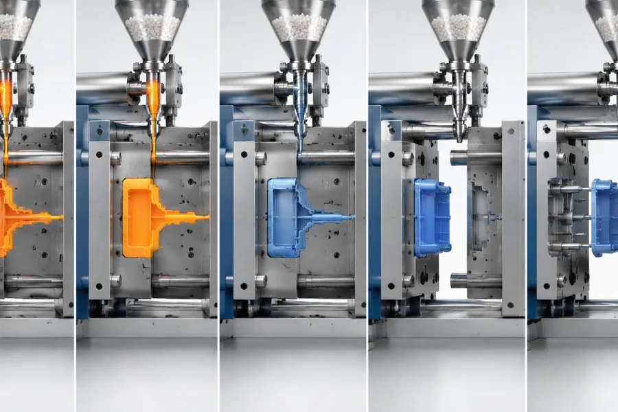
During filling, the injection screw pushes molten plastic through the nozzle, runner system, and gate into the mold cavity. A simplified relationship is:
t_fill = V_fill / Q_avg
Where V_fill is the volume delivered during filling in cm³ and Q_avg is the actual average volumetric flow rate in cm³/s.
Filling time depends on the injection velocity profile, melt viscosity, gate and runner restrictions, pressure limits, and velocity-to-pressure transfer position. The machine’s maximum rated injection speed should not be treated as the actual average flow rate.
Increasing injection speed may shorten filling time, but excessive speed can cause flash, jetting, trapped-gas burns, or excessive shear heating.
After filling, the machine switches from velocity-controlled injection to pressure-controlled packing and holding. Holding pressure supplies additional molten material through the gate to compensate for shrinkage as the polymer cools.
The effective holding period depends on gate freeze. Before the gate seals, additional material can enter the cavity and affect part weight, dimensions, and internal structure. After effective gate closure, extending holding time generally provides little additional packing benefit.
Releasing holding pressure before the gate seals can allow molten material to flow back toward the runner, contributing to shrinkage, sink marks, internal voids, or dimensional variation. The appropriate holding time depends on part thickness, gate dimensions, material behavior, and melt and mold temperatures.
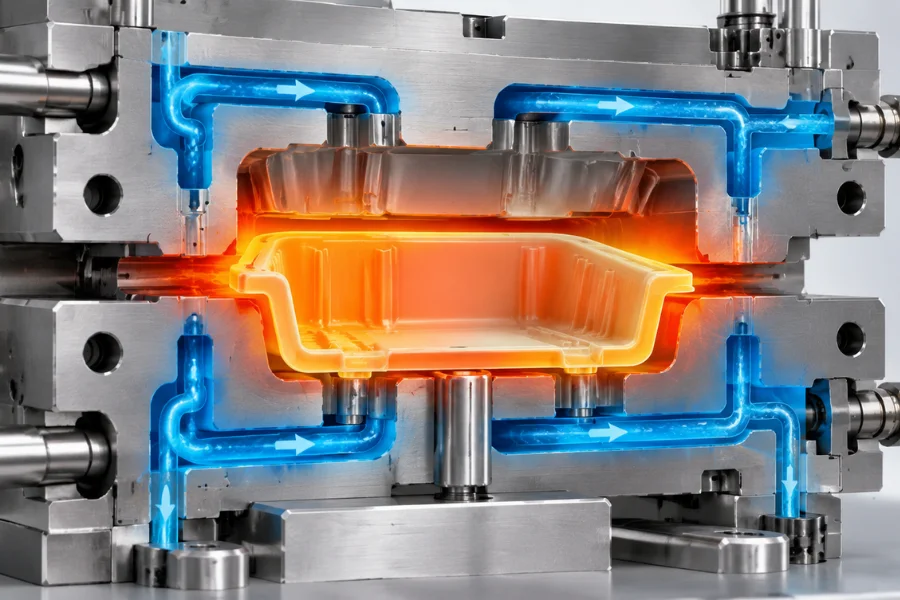
Heat transfers from the polymer into the mold and then into the cooling system. The part must develop sufficient stiffness and dimensional stability before ejection; otherwise, it may deform under ejector forces or warp after removal.
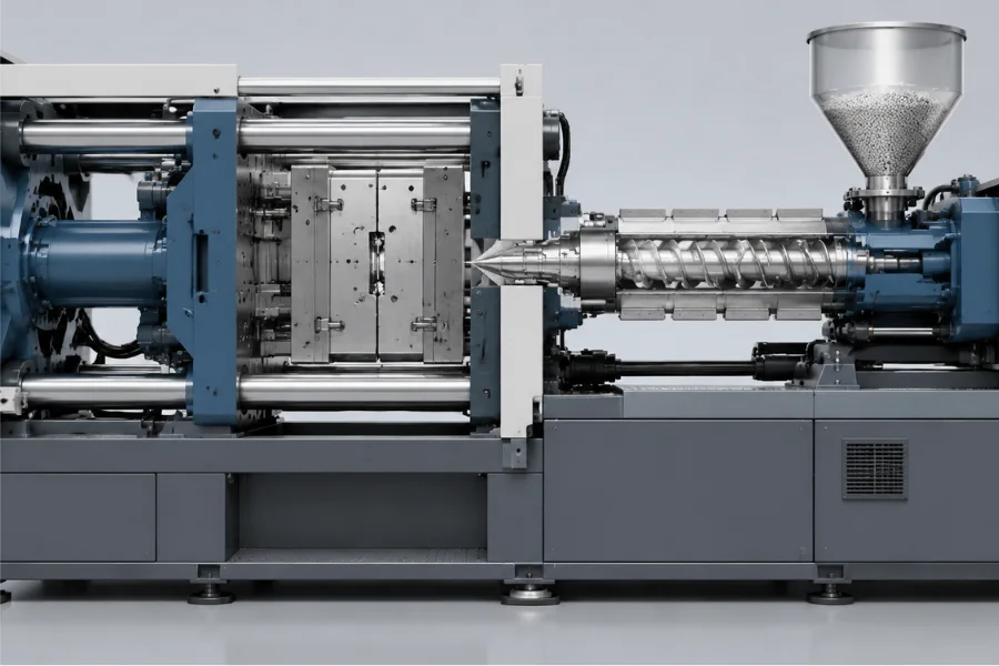
Meanwhile, the screw can rotate and retract to prepare material for the next shot. Because screw recovery often overlaps with cooling, it should not automatically be counted as a separate full-duration stage. It becomes a cycle-time bottleneck when recovery finishes later than the machine’s other required operations.
Auxiliary time depends on mold travel, ejector movement, side actions, robotic part removal, and any manual insert-loading operations. A simple two-plate mold with automatic ejection may require less time than a mold with multiple slides, unscrewing mechanisms, or manually positioned inserts.
Reducing movement time helps only when the mold can operate safely and parts can be released reliably without damage.
A simplified injection molding cycle time formula is:
T_cycle = T_injection + T_cooling + T_auxiliary
Here, injection time includes filling and holding, cooling represents the additional nonoverlapping cooling interval, and auxiliary time includes mold movements and ejection.
The formula is valid only when each term represents a distinct time interval. If cooling is measured from the beginning of injection, rather than after holding, the overlapping time must be accounted for to avoid double-counting.
Consider a hypothetical process with the following timing.
| Cycle stage | Time |
|---|---|
| Filling | 2 seconds |
| Packing and holding | 8 seconds |
| Additional cooling after holding | 18 seconds |
| Mold opening, ejection, and closing | 6 seconds |
| Total cycle time | 34 seconds |
The total is:
T_cycle = 2 + 8 + 18 + 6 = 34 seconds
This example assumes screw recovery finishes within the 18-second additional cooling interval and does not delay the next cycle.
If recovery instead takes 21 seconds, and the machine cannot begin the next operation until recovery and cooling are complete, the cycle becomes:
T_cycle = 2 + 8 + max(18, 21) + 6 = 37 seconds
This calculation assumes recovery and remaining cooling occur in parallel, followed by auxiliary operations. Actual machine sequences may differ, so production estimates should use recorded cycle timestamps and the machine’s control logic.
Before tooling is built, an initial estimate should account for:
Historical data from comparable parts can provide a starting point, but differences in geometry, gate design, resin grade, and mold construction must be considered. Mold filling and cooling simulations can further refine estimates for complex or high-volume projects.
Cooling is often a major component of the cycle for thick-walled thermoplastic parts. The required time depends on heat transfer through the polymer, mold temperature, cooling-system performance, and the stiffness required for safe ejection.
For a simplified flat plastic section under comparable thermal conditions, cooling time increases approximately with the square of the complete wall thickness:
t_c ∝ s²
Here, s is the full wall thickness. Under the same idealized conditions, increasing wall thickness from 2 mm to 4 mm can increase calculated cooling time by approximately four times.
This relationship is a useful first-order estimate, not an exact prediction for complex parts. Ribs, bosses, corners, variable wall thickness, and localized mold temperatures can change actual cooling behavior.
A simplified one-dimensional heat-transfer model for a flat plastic section is:
t_c ≈ [s² / (π² × α_eff)] × ln[(4 / π) × ((T_m − T_w) / (T_e − T_w))]
Where:
| Symbol | Definition | Unit |
|---|---|---|
| t_c | Estimated cooling time | s |
| s | Complete wall thickness | m |
| α_eff | Effective polymer thermal diffusivity | m²/s |
| T_m | Initial polymer temperature | °C |
| T_w | Mold wall temperature | °C |
| T_e | Selected center-temperature criterion for ejection | °C |
The model assumes approximately uniform initial temperature, an effective constant thermal diffusivity, and a constant mold-wall temperature. The selected temperatures must satisfy the model’s physical assumptions and produce a meaningful positive cooling time.
Actual cooling can differ because polymer properties vary with temperature, crystallization releases heat, and complex geometries create nonuniform temperature fields. The ejection-temperature criterion also requires engineering judgment because a part does not need to reach a uniform temperature throughout its thickness before it can necessarily be ejected safely.
The calculated cooling time is a thermal estimate, not automatically the additional cooling interval programmed into the machine. Filling and holding may already account for part of the elapsed cooling process.
Heat removal depends on the temperature difference between the polymer and mold, thermal contact at the cavity surface, and the mold’s ability to transfer heat into the cooling system. Because these conditions change during the cycle, lowering coolant temperature does not necessarily produce a proportional reduction in cooling time.
Mold temperature also affects filling, surface appearance, residual stress, crystallization, shrinkage, and dimensional stability. The objective is to maintain an appropriate and sufficiently uniform temperature while removing heat efficiently.
Thermal diffusivity influences how quickly temperature changes propagate through the polymer, while melt temperature affects the heat introduced into the mold. Crystallization behavior, resin grade, and fillers can also change cooling, shrinkage, and processing requirements.
ABS, PP, PC, PA, and POM can have different molding cycles even at similar nominal wall thicknesses. However, resin type alone cannot determine cycle time because geometry, gate design, mold temperature, and ejection requirements also affect the result.
Thick sections retain heat longer and may delay ejection even after adjacent thin walls have cooled sufficiently. Common bottlenecks include thick bosses connected to thin walls, oversized ribs, large solid sections, abrupt wall-thickness transitions, and deep features that complicate cooling.
Core out unnecessary material or redesign thick sections where structural requirements permit. Wall thickness should not be minimized without considering strength, stiffness, flow length, assembly requirements, and dimensional tolerances.
Cooling-channel layout affects both heat removal and temperature uniformity. Channel spacing, distance from the cavity surface, coolant flow rate, and inlet-to-outlet temperature differences determine how effectively the system manages heat.
Channels should address thick sections, deep cores, and gate regions where heat may accumulate. Excessive local cooling can create uneven shrinkage even when the average mold temperature decreases.
Gate dimensions also influence packing time. A larger or thicker gate may remain open longer, while a smaller gate may freeze sooner but restrict filling and pressure transmission. Gate selection must balance filling, packing, part quality, and cycle requirements rather than optimize freeze time alone.
Machine plasticizing capacity, clamp movement, and control settings can limit the achievable cycle. Mold slides, lifters, unscrewing mechanisms, manual inserts, and robotic handling may add operations or waiting time.
For automated production, coordinate robot movements and part removal with the machine sequence to reduce unnecessary delays without compromising safe mold operation.
The correct optimization target is the operation that limits the actual machine cycle. If screw recovery finishes after cooling, improving cooling alone may not shorten the cycle because plasticizing remains the bottleneck.
Reduce unnecessary thick sections, use properly designed ribs instead of increasing entire wall thicknesses, and review bosses for localized heat accumulation. Adequate draft can also improve ejection reliability.
These changes must preserve mechanical performance, dimensional requirements, and moldability. Design-stage changes generally provide more flexibility than modifications to an existing mold.
Conventional drilled cooling channels may be adequate for simple geometries. For complex parts, conformal cooling channels can follow the molded geometry more closely and improve cooling access to difficult regions.
Conformal cooling is not automatically the most economical solution. Its value depends on the original thermal bottleneck, production volume, tooling cost, and achievable cycle improvement.
Before modifying a mold, inspect coolant flow, blocked passages, temperature-control settings, and temperature differences across the tool. Correcting an existing flow or temperature-distribution problem may be more practical than replacing the cooling design.
A gate freeze study identifies when additional holding time stops providing meaningful material compensation through the gate.
Mold parts at several holding-time settings while keeping holding pressure, transfer position, melt temperature, mold temperature, and other relevant conditions stable. Weigh the parts using consistent trimming and measurement procedures so gate or runner variation does not distort the comparison.
When part weight reaches a repeatable plateau, additional holding time generally provides little further packing benefit. This identifies an effective packing endpoint, not automatically the final production setting. Confirm the selected setting through dimensional measurements and inspection for sink marks, voids where relevant, and other specified quality requirements.
Reduce cooling time incrementally while monitoring part deformation during ejection, post-ejection warpage, dimensional variation, ejector marks, and part sticking.
If shorter cooling causes deformation or inconsistent dimensions, the process may have reached a practical limit under the existing tooling and material conditions. Further improvement may require changes to part geometry, cooling-channel design, or mold-temperature distribution rather than another machine-setting adjustment.
Review mold-opening travel, ejector strokes, robot coordination, and screw recovery. If recovery delays the next shot, investigate plasticizing performance and the available overlap with cooling.
Increasing screw speed or back pressure without evaluating melt quality can cause excessive shear heating, degradation, or inconsistent plasticizing. Any mechanical optimization must preserve safe mold movement, reliable part removal, and consistent melt preparation.
| Optimization method | Potential benefit | Quality risk to verify |
|---|---|---|
| Reduce holding time | Eliminate unnecessary packing time | Sink marks, voids, dimensional variation |
| Reduce cooling time | Shorten mold residence time | Warpage, ejection deformation |
| Increase injection speed | Reduce filling time | Flash, burn marks, shear heating |
| Improve cooling channels | Increase heat removal and uniformity | Uneven mold temperatures |
| Adjust gate dimensions | Improve filling or packing behavior | Gate marks, premature freeze, pressure loss |
| Optimize ejection | Reduce auxiliary time | Ejector marks, sticking, part damage |
A shorter cycle is beneficial only if the process continues to meet product specifications under normal production variation.
For a multi-cavity mold, theoretical production rate is:
Parts per Hour = (3600 × n) / T_cycle
Where n is the number of parts produced per cycle and T_cycle is cycle time in seconds.
Consider a four-cavity mold operating at a 40-second cycle:
Parts per Hour = (3600 × 4) / 40 = 360
Reducing the cycle to 36 seconds gives:
Parts per Hour = (3600 × 4) / 36 = 400
| Production parameter | Initial cycle | Optimized cycle |
|---|---|---|
| Cycle time | 40 seconds | 36 seconds |
| Mold cavities | 4 | 4 |
| Theoretical cycles per hour | 90 | 100 |
| Theoretical parts per hour | 360 | 400 |
A 10% reduction in cycle time increases theoretical hourly output by approximately 11.1%. Actual good-part production will be lower when downtime and rejected parts are included.
Machine processing cost per part can be estimated as:
Machine Cost per Part = (R × T_cycle) / (3600 × n)
Here, R is the assumed machine hourly rate.
At $60 per hour with four productive cavities:
| Cycle time | Machine cost per part |
|---|---|
| 40 seconds | $0.167 |
| 36 seconds | $0.150 |
These figures assume continuous production with all cavities producing acceptable parts. They exclude material, tooling amortization, secondary operations, and other costs not included in the hourly rate.
To account for scheduled production time that includes downtime and rejected parts, a simplified machine cost per good part is:
Machine Cost per Good Part = (R × T_cycle) / (3600 × n × A × Y)
Where A is production time availability and Y is the good-part yield, both expressed as decimals.
This adjustment assumes the hourly rate applies to scheduled production time and that availability and yield use consistent measurement periods. If the machine rate already includes downtime allowances, the same losses should not be applied again.
A calculated cycle time provides an initial target; mold trials establish whether it can be achieved consistently without compromising quality.
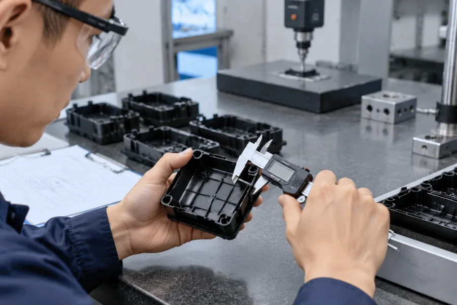
Part measurements should follow a consistent conditioning procedure because some molded dimensions continue to change after ejection. Critical applications may require additional functional or dimensional inspections.
A faster process that increases rejection rates may deliver less usable production capacity. The appropriate target is the shortest repeatable cycle that consistently produces conforming parts.
Injection molding cycle time can range from a few seconds for certain thin-wall products to several minutes for thick or complex components. There is no universal average suitable for every application. Material properties, wall thickness, mold cooling, holding requirements, and machine operations determine the actual cycle.
Add the nonoverlapping durations of filling, packing and holding, additional cooling, and auxiliary operations such as mold opening and ejection. When screw recovery overlaps with cooling, count only any additional delay it creates. Actual machine-cycle records provide a more reliable production estimate than adding stages that may overlap.
Thicker plastic sections require more time for heat to travel from the interior toward the mold surface. In a simplified flat-plate model, cooling time is approximately proportional to wall thickness squared. Actual results also depend on polymer thermal properties, mold temperature, cooling-channel design, and ejection requirements.
Identify the operation that limits the actual machine cycle. Common improvements include reducing unnecessary wall thickness, correcting cooling-channel problems, determining effective holding time through gate freeze studies, and optimizing machine movements. Validate each adjustment against dimensional accuracy, surface quality, and ejection reliability.
A shorter cycle does not necessarily reduce quality when the process remains within a validated operating window. Insufficient holding can cause shrinkage-related defects, while premature ejection can cause warpage or deformation. Verify dimensions, appearance, and relevant functional requirements whenever cycle settings change.
Injection molding cycle time should be optimized by identifying the operations that limit the actual machine cycle. Cooling performance, gate freeze, screw recovery, and ejection requirements must be evaluated alongside dimensional stability and part quality.
Calculations provide an initial target, while controlled mold trials establish the shortest repeatable cycle that consistently produces acceptable parts.