Physical Address
304 North Cardinal St.
Dorchester Center, MA 02124
Physical Address
304 North Cardinal St.
Dorchester Center, MA 02124
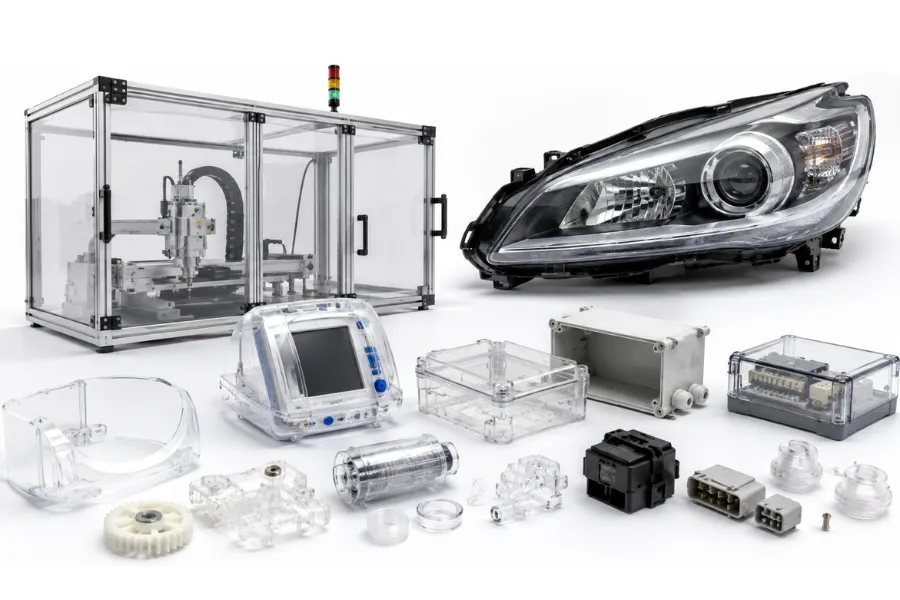
Polycarbonate (PC) is one of the most widely specified engineering thermoplastics because it combines impact resistance, optical clarity, dimensional stability, and thermal performance in a single material. These characteristics make it a preferred choice for products ranging from medical device housings and industrial equipment to automotive lighting and electrical enclosures.
However, selecting polycarbonate alone does not guarantee a successful product. Many production issues—including stress cracking, silver streaks, dimensional variation, poor transparency, and premature failure—are usually caused by design decisions or manufacturing conditions rather than the resin itself. Factors such as mold temperature, drying, wall thickness, gate location, and residual stress often determine whether a PC component performs reliably throughout its service life.
This guide explains what polycarbonate is, its engineering properties, processing characteristics, common applications, material comparisons, and practical Design for Manufacturing (DFM) recommendations. Rather than simply introducing the material, it focuses on the engineering decisions that help manufacturers improve product quality, production stability, and long-term reliability.
Polycarbonate (PC) is a high-performance thermoplastic engineering plastic containing carbonate groups within its molecular structure. Unlike commodity plastics that are primarily selected for low manufacturing cost, polycarbonate is engineered for applications requiring a balance of mechanical strength, transparency, dimensional precision, and durability.
One of its defining characteristics is its ability to combine approximately 90% visible light transmission with exceptional impact resistance. This combination allows engineers to replace glass in many applications while significantly improving impact safety and reducing product weight.
Polycarbonate is also recognized for its stable molding shrinkage of approximately 0.5–0.8%, making it suitable for precision injection molding where dimensional repeatability is essential. Properly processed components can achieve excellent dimensional accuracy and maintain stable performance over a broad operating temperature range, from extremely low temperatures to continuous service around 120°C.
Unlike materials optimized for only one property, polycarbonate delivers a balanced combination of toughness, thermal stability, electrical insulation, and optical performance. This versatility explains why it is widely used across industrial, medical, electronic, and automotive manufacturing.
| Property | Typical Value | Engineering Significance |
|---|---|---|
| Material Type | Thermoplastic engineering plastic | Suitable for precision injection molding |
| Density | 1.20 g/cm³ | Lightweight with high structural efficiency |
| Light Transmission | Approximately 90% | Suitable for transparent engineering components |
| Molding Shrinkage | 0.5–0.8% | Excellent dimensional stability |
| Long-Term Service Temperature | Up to 120°C | Reliable performance under elevated temperatures |
| Impact Resistance | Excellent | Among the highest of engineering thermoplastics |
| Electrical Properties | Stable over a wide temperature range | Reliable insulation performance |
Rather than evaluating these properties individually, engineers typically consider how they work together throughout the product lifecycle. A material offering excellent impact resistance but poor dimensional stability may create assembly problems, while a material with excellent transparency but poor toughness may fail under service conditions. Polycarbonate remains popular because it provides a well-balanced engineering solution instead of maximizing only one characteristic.
The table below summarizes the most important engineering recommendations for polycarbonate during product development and manufacturing.
| Engineering Item | Typical Recommendation |
|---|---|
| Preferred Manufacturing Process | Injection Molding |
| Material Drying Required | Yes, always before molding |
| Typical Shrinkage | 0.5–0.8% |
| Recommended Mold Temperature | 90–110°C |
| Typical Barrel Temperature | 240–290°C |
| Recommended Wall Thickness | 2–4 mm |
| Corner Radius | ≥50% of wall thickness |
| Draft Angle | Minimum 1° (increase for textured surfaces) |
| Suitable for Precision Components | Excellent |
| Typical Industries | Medical, Electrical, Industrial, Automotive |
This quick-reference guide can be used during early Design for Manufacturing (DFM) reviews before detailed mold design begins.
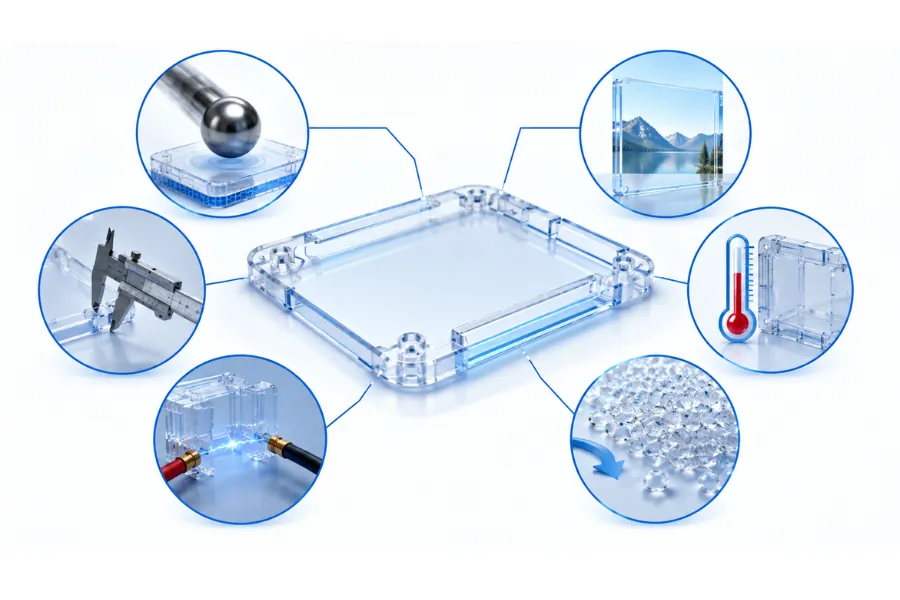
Polycarbonate is selected because several engineering characteristics complement one another throughout manufacturing and product operation.
Polycarbonate possesses one of the highest impact strengths among thermoplastic engineering plastics. Instead of fracturing under sudden impact, it absorbs significant impact energy while maintaining structural integrity.
Applications benefiting from this property include:
Another important advantage is dimensional stability.
Because PC maintains relatively consistent shrinkage during molding, manufacturers can achieve better dimensional repeatability, improved process capability (Cp/Cpk), and more reliable assembly across high-volume production.
For precision assemblies, consistent dimensions often contribute more to product quality than simply increasing mechanical strength.
Polycarbonate maintains mechanical performance across a broad temperature range.
Key characteristics include:
These characteristics explain why PC is frequently used for connectors, relay housings, electrical control systems, laboratory equipment, and industrial electronics.
Unlike some plastics whose electrical performance deteriorates after moisture exposure, properly processed polycarbonate maintains stable dielectric properties under a wide range of environmental conditions.
Transparency is another major advantage.
Unlike opaque engineering plastics such as POM or nylon, polycarbonate combines optical clarity with structural durability.
Typical applications include:
However, optical quality depends heavily on manufacturing quality.
Even high-grade resin cannot compensate for poor mold polishing, unstable melt temperatures, trapped gas, or insufficient drying. These manufacturing variables often determine the final transparency more than the material itself.
Polycarbonate provides good resistance to several common industrial substances.
Generally resistant to:
However, engineers should avoid prolonged exposure to:
These chemicals may accelerate environmental stress cracking and reduce long-term durability.
Material compatibility should therefore be evaluated during product design rather than after production begins.
No engineering plastic performs perfectly under every condition, and polycarbonate is no exception.
Although PC offers outstanding toughness and dimensional stability, these advantages require more demanding processing conditions than many commodity plastics.
Its relatively high melt viscosity increases filling resistance, particularly in thin-wall or long-flow components. Stable production therefore depends on maintaining appropriate melt temperature, mold temperature, and gate design instead of relying solely on higher injection pressure.
Another important consideration is stress cracking.
Many engineers assume cracking indicates insufficient material strength.
In reality, cracking is more often caused by residual molding stress created through:
Successful polycarbonate products therefore depend on integrating material selection, product design, tooling, and processing into a single engineering strategy.
| Design Item | Recommended Practice | Engineering Benefit |
|---|---|---|
| Wall Thickness | 2–4 mm where possible | Balance filling, cooling and stiffness |
| Wall Thickness Variation | Keep transitions gradual | Reduce differential shrinkage |
| Corner Radius | ≥50% of wall thickness | Reduce stress concentration |
| Rib Thickness | 50–60% of adjoining wall | Minimize sink marks |
| Gate Location | Thickest section | Improve packing efficiency |
| Mold Surface Finish | Mirror polish for optical components | Improve transparency |
| Vent Depth | 0.01–0.03 mm | Eliminate trapped gas |
These recommendations are not fixed rules, but they provide a practical starting point for minimizing manufacturing risks during product development.
Many manufacturers initially focus on reducing cycle time.
However, experienced molding engineers often prioritize process stability instead.
For example, maintaining a mold temperature between 90°C and 110°C generally increases cycle time compared with molding at lower temperatures. At first glance, this appears less efficient.
In practice, however, stable mold temperatures reduce residual stress, improve dimensional consistency, lower scrap rates, and decrease customer complaints caused by delayed cracking.
The result is often a lower overall manufacturing cost despite a slightly longer molding cycle.
This illustrates an important engineering principle:
The lowest production cost is rarely achieved through the shortest cycle time. It is achieved through the most stable manufacturing process.
Polycarbonate has remained one of the world’s leading engineering plastics because it solves multiple engineering problems simultaneously. Instead of optimizing only one property, it delivers an effective balance of impact resistance, transparency, dimensional stability, thermal performance, and electrical insulation.
From an engineering perspective, this balance often allows a single molded component to replace more complex metal, glass, or multi-material assemblies, simplifying manufacturing while reducing assembly operations.
However, these performance advantages come with processing requirements that engineers must consider during both product design and mass production.
| Advantage | Engineering Benefit | Manufacturing Benefit | Typical Applications |
|---|---|---|---|
| Exceptional impact resistance | Resists accidental impacts without brittle fracture | Reduces field failures and warranty claims | Machine guards, protective covers, automotive lighting |
| High transparency | Approximately 90% visible light transmission | Eliminates secondary transparent assemblies | Optical covers, lenses, equipment windows |
| Low and stable shrinkage | Excellent dimensional repeatability | Improves assembly consistency and process capability | Electronic housings, medical devices |
| High thermal stability | Reliable operation up to approximately 120°C | Suitable for elevated-temperature environments | Industrial equipment, electrical systems |
| Stable electrical insulation | Consistent dielectric performance | Reliable electrical safety | Connectors, relay housings, terminal blocks |
| Lightweight engineering material | High strength-to-weight ratio | Reduces transportation and assembly weight | Medical equipment, portable products |
Unlike many engineering plastics that excel in one category while sacrificing another, polycarbonate provides a balanced solution that supports both product performance and manufacturing reliability.
Successful material selection also requires understanding where polycarbonate introduces engineering challenges.
| Limitation | Engineering Impact | Recommended Engineering Solution |
|---|---|---|
| High melt viscosity | More difficult cavity filling | Optimize melt temperature, gate design, and runner balance |
| Moisture sensitivity during molding | Silver streaks, bubbles, molecular degradation | Implement strict drying procedures |
| Stress cracking tendency | Long-term reliability may decrease | Reduce residual stress through better design and processing |
| Limited chemical resistance | Unsuitable for prolonged exposure to strong alkalis or aromatic solvents | Verify chemical compatibility during design |
| Higher processing temperature | Increased energy consumption | Optimize thermal control and cycle balance |
| Longer production cycle | Higher manufacturing cost per part | Improve cooling efficiency instead of reducing mold temperature |
Many of these limitations are not material defects but manufacturing considerations. When incorporated into DFM reviews early in development, they can usually be managed without compromising product performance.
Instead of asking whether polycarbonate is “better” than another plastic, engineers typically evaluate whether it is the most appropriate material for a specific application.
The following decision matrix reflects a practical engineering selection process.
| Product Requirement | Recommended Choice | Engineering Reason |
|---|---|---|
| High impact resistance | ✓ Polycarbonate | Outstanding toughness |
| Transparent structural component | ✓ Polycarbonate | Combines clarity with mechanical strength |
| Precision injection molded component | ✓ Polycarbonate | Low and predictable shrinkage |
| Electrical insulation | ✓ Polycarbonate | Stable dielectric properties |
| Excellent scratch resistance | Acrylic (PMMA) | Better surface hardness |
| Continuous chemical exposure | PETG or other chemically resistant materials | Better compatibility in some environments |
| Low-cost structural housing | ABS | Lower material and processing cost |
| High structural stiffness | Glass Fiber Reinforced PC | Improved rigidity and dimensional stability |
This decision process illustrates an important engineering principle:
Material selection should always begin with functional requirements, followed by manufacturability, long-term reliability, and total production cost.
A simplified decision process often looks like this:
Need a transparent component?
→ No → Consider ABS or another opaque engineering plastic.
→ Yes
Will the component experience significant impact loading?
→ Yes → Polycarbonate is generally the preferred choice.
→ No
Is maximum scratch resistance more important than impact strength?
→ Yes → Acrylic (PMMA) may be more suitable.
→ No
Will the product operate in chemically aggressive environments?
→ Yes → Evaluate PETG or other chemically resistant engineering plastics.
→ No → Polycarbonate remains an excellent all-around engineering solution.
This type of engineering decision logic is frequently used during early product development to reduce unnecessary design iterations.
Polycarbonate is widely used across multiple industries because it satisfies several engineering requirements simultaneously rather than excelling in only one property.
In industrial machinery, polycarbonate is commonly used for components that require dimensional stability, impact resistance, and long service life.
Typical examples include:
For these applications, maintaining dimensional consistency throughout production is often as important as achieving high mechanical strength.
Because of its stable electrical insulation and thermal performance, polycarbonate is frequently specified for:
Many electrical products experience repeated heating and cooling cycles during operation. Polycarbonate’s dimensional stability helps maintain reliable assembly throughout these temperature changes.
Unlike many engineering plastics, polycarbonate combines optical clarity with outstanding toughness.
Typical applications include:
For these products, manufacturing quality often determines final optical performance. Mold surface finish, moisture control, and stable processing conditions are equally important as selecting the correct resin.
Medical and industrial equipment frequently requires components that combine strength, dimensional precision, and durability.
Typical applications include:
Many of these products also undergo repeated assembly, cleaning, or sterilization cycles, making dimensional repeatability essential for long-term reliability.
Despite its relatively high processing cost, polycarbonate continues to be widely specified because it often lowers the total cost of ownership.
Instead of evaluating only raw material cost, manufacturers increasingly consider:
A material that costs more to process may ultimately become the lower-cost solution if it significantly reduces failures after production.
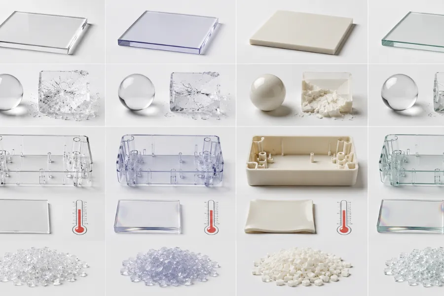
Engineers rarely compare materials based on only one property. Instead, they evaluate how each material affects product performance, manufacturability, tooling investment, and lifecycle cost.
| Property | Polycarbonate | Acrylic (PMMA) | ABS | PETG |
|---|---|---|---|---|
| Impact Resistance | Excellent | Moderate | Good | Good |
| Optical Clarity | Excellent | Excellent | Opaque | Excellent |
| Heat Resistance | Excellent | Moderate | Moderate | Moderate |
| Dimensional Stability | Excellent | Good | Good | Good |
| Injection Molding Precision | Excellent | Good | Excellent | Good |
| Processing Difficulty | High | Moderate | Easy | Moderate |
| Relative Manufacturing Cost | High | Medium | Low | Medium |
| Typical Industrial Use | Precision engineering | Optical products | Consumer housings | Packaging and transparent components |
| Primary Design Objective | Recommended Material |
|---|---|
| Maximum impact resistance | Polycarbonate |
| Highest optical appearance | Acrylic |
| Lowest manufacturing cost | ABS |
| Better chemical compatibility | PETG |
| Precision transparent engineering component | Polycarbonate |
| Structural component requiring high stiffness | Glass Fiber Reinforced PC |
From an engineering perspective, there is rarely a universally “best” plastic.
The optimal material is the one that delivers the required mechanical performance, manufacturing stability, service life, and production cost for the intended application. This broader engineering perspective is why polycarbonate remains one of the most important engineering plastics in modern manufacturing.
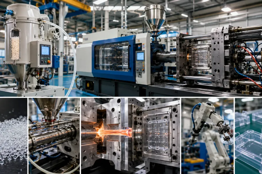
Injection molding is the preferred manufacturing process for polycarbonate because it enables complex geometries, tight dimensional tolerances, and repeatable mass production. However, compared with materials such as ABS or polypropylene, PC has a much narrower processing window. Its high melt viscosity, elevated processing temperatures, and sensitivity to moisture require engineers to control the entire molding system rather than adjusting individual parameters independently.
In production environments, defects such as silver streaks, bubbles, stress cracking, dimensional variation, and short shots are rarely caused by the resin itself. More often, they originate from inadequate drying, unstable mold temperatures, poor gate design, or improper process control. For this reason, successful polycarbonate molding should be approached as a combination of material science, tooling design, and process engineering.
Although polycarbonate has relatively low moisture absorption compared with some engineering plastics, it becomes highly sensitive to residual moisture at molding temperatures above 240°C.
Water trapped inside the pellets causes hydrolysis during plasticization, permanently reducing molecular weight before the material even enters the mold cavity. This degradation cannot be reversed later in the process.
Common moisture-related defects include:
For optical or medical components, even slight moisture contamination may cause parts to fail inspection despite meeting dimensional requirements.
Experienced molding engineers rarely begin troubleshooting by changing injection pressure.
Instead, they usually verify three questions first:
In many factories, inconsistent resin handling creates more production problems than incorrect machine settings.
The following processing window provides a practical starting point for standard injection molding of polycarbonate.
| Parameter | Typical Range | Engineering Purpose |
|---|---|---|
| Injection Machine | Screw type | Stable plasticization and homogeneous melt |
| Screw Speed | 20–40 rpm | Minimize excessive shear heating |
| Nozzle Temperature | 230–250°C | Maintain stable melt flow |
| Front Barrel Temperature | 240–280°C | Improve filling capability |
| Middle Barrel Temperature | 260–290°C | Complete plasticization |
| Rear Barrel Temperature | 240–270°C | Stable feeding conditions |
| Mold Temperature | 90–110°C | Improve flow, packing, and dimensional stability |
| Injection Pressure | 80–130 MPa | Complete cavity filling |
| Holding Pressure | 40–50 MPa | Reduce shrinkage variation |
| Cooling Time | 20–50 s | Depends on wall thickness |
| Typical Cycle Time | 50–130 s | Influenced by cooling efficiency and part geometry |
These values should be treated as engineering reference ranges rather than universal production settings. Final processing conditions should always be optimized through mold trials and validated according to part geometry, quality requirements, and production capability.
Many engineers initially assume that filling problems can be solved simply by increasing injection pressure.
For polycarbonate, this is often incorrect.
Because PC exhibits relatively high melt viscosity, increasing melt temperature and maintaining proper mold temperature generally improve flow much more effectively than increasing pressure alone.
Maintaining the mold between 90°C and 110°C provides several important benefits:
This is why many manufacturers use oil temperature controllers or electric mold heaters rather than relying solely on conventional cooling water.
Some manufacturers attempt to shorten production cycles by lowering mold temperature.
Although this may improve hourly output, it often introduces hidden quality costs:
For precision molded products, stable mold temperature usually produces a lower overall manufacturing cost than the shortest possible cycle time.
Another common production mistake is treating injection pressure as the primary solution for molding defects.
In reality, experienced process engineers generally optimize parameters in the following sequence:
This sequence creates a wider processing window and significantly improves production repeatability.
Simply increasing injection pressure may temporarily eliminate a short shot, but it also increases:
Optimizing thermal conditions usually produces more stable results with fewer secondary problems.
Polycarbonate is often viewed as an expensive engineering plastic, but material price represents only part of the manufacturing cost.
Compared with lower-temperature plastics, PC generally requires:
These factors increase the direct cost of molding each component.
However, many manufacturers continue choosing polycarbonate because improved product reliability frequently offsets these additional production expenses.
For high-value products such as medical devices, industrial equipment, and precision electronics, reducing scrap, warranty claims, and field failures often delivers greater financial benefits than minimizing cycle time.
One of the biggest differences between average molding projects and successful production programs is the amount of DFM work completed before tooling begins.
The following design review items should be evaluated during product development.
| DFM Item | Engineering Recommendation | Manufacturing Benefit |
|---|---|---|
| Gate Location | Position at the thickest section whenever possible | Improve packing and reduce sink marks |
| Flow Length | Avoid excessive flow paths | Reduce filling pressure requirements |
| Wall Thickness | Maintain uniform sections | Minimize shrinkage variation |
| Weld Line Location | Keep away from highly loaded areas | Improve structural strength |
| Cooling Balance | Design uniform cooling circuits | Reduce warpage and cycle variation |
| Vent Position | Vent end-of-fill locations adequately | Prevent gas traps and burn marks |
| Mold Maintenance | Design for easy cleaning and servicing | Improve long-term production stability |
Performing these reviews before mold manufacturing typically reduces tooling modifications, shortens production ramp-up, and lowers overall project cost.
Successful polycarbonate molding depends heavily on tooling design because the material is less forgiving than many commodity plastics.
Gate design influences pressure distribution, molecular orientation, residual stress, and packing efficiency.
| Gate Type | Recommended Application | Engineering Advantage |
|---|---|---|
| Direct Gate | Thick-wall and large components | Excellent packing and shrinkage compensation |
| Edge Gate | General industrial parts | Simple processing and balanced filling |
| Pin Gate | Small precision components | Suitable for automated production |
| Tab Gate | High-viscosity PC components | Reduces jetting and localized stress concentration |
Among these options, tab gates deserve particular attention for polycarbonate because they allow the melt to stabilize before entering the cavity, reducing shear stress and improving long-term durability.
Because molten polycarbonate flows less easily than lower-viscosity plastics, trapped air must be removed efficiently.
Typical vent depth:
0.01–0.03 mm
Poor venting commonly results in:
Instead of relying on one large vent, engineers generally distribute multiple vents at end-of-fill locations to improve cavity evacuation.
Adequate draft reduces ejection force and minimizes residual stress.
Recommended values include:
| Feature | Typical Recommendation |
|---|---|
| Cavity Draft | 35’–40′ |
| Core Draft | 30’–50′ |
| Textured Surfaces | Increase draft beyond standard values |
Although reducing draft may appear beneficial for appearance, it often increases ejection force and raises the likelihood of stress cracking.
Many long-term failures originate from part geometry rather than processing conditions.
Typical engineering recommendations include:
| Design Feature | Recommended Practice | Engineering Benefit |
|---|---|---|
| Wall Thickness | 2–4 mm | Balanced filling and cooling |
| Thickness Transition | Smooth and gradual | Reduce differential shrinkage |
| Corner Radius | ≥50% of wall thickness | Lower stress concentration |
| Rib Thickness | 50–60% of nominal wall | Reduce sink marks |
| Gate Position | Thickest wall section | Improve packing efficiency |
Stress cracking is one of the most misunderstood failure modes in polycarbonate products.
Many engineers initially attribute cracking to insufficient material strength.
In practice, delayed cracking usually develops from the combined effects of:
This explains why simply changing the resin grade rarely solves the problem.
The most effective solution is usually improving part geometry, thermal control, and mold design before attempting to modify processing parameters.
Successful troubleshooting begins by identifying the engineering source of the defect rather than adjusting machine settings indiscriminately.
| Defect | Primary Root Cause | Recommended Engineering Solution |
|---|---|---|
| Silver Streaks | Moisture contamination | Thorough resin drying |
| Internal Bubbles | Moisture or insufficient venting | Improve drying and vent layout |
| Stress Cracking | Residual stress and poor geometry | Increase mold temperature, enlarge radii, optimize design |
| Strength Reduction | Hydrolysis or overheating | Control moisture and barrel temperature |
| Short Shot | High viscosity, low mold temperature, undersized gate | Increase melt temperature, enlarge gate, optimize thermal conditions |
| Warpage | Uneven cooling | Balance cooling channels and mold temperature |
Rather than treating every defect as a machine adjustment problem, experienced manufacturers classify defects into four engineering categories:
This systematic troubleshooting approach improves process capability, reduces scrap, and creates a more stable manufacturing process over long production runs.
Selecting the appropriate polycarbonate grade is just as important as selecting polycarbonate itself. Although all PC materials share the same basic characteristics, different grades are engineered to optimize specific performance requirements such as optical clarity, flame resistance, structural stiffness, dimensional stability, or processing efficiency.
Instead of asking “Which grade has the highest strength?”, experienced engineers typically evaluate the product’s functional requirements first.
Questions commonly asked during material selection include:
Answering these questions early helps reduce tooling revisions, improves manufacturability, and minimizes production risk.
| Grade | Primary Characteristics | Typical Applications | Engineering Trade-off |
|---|---|---|---|
| General-Purpose PC | Excellent balance of toughness, transparency, and dimensional stability | Industrial housings, machine covers, protective components | Higher processing temperatures than commodity plastics |
| Optical-Grade PC | High light transmission with minimal optical distortion | Lenses, light guides, medical optics, instrument windows | Requires superior mold polishing and tighter process control |
| Flame-Retardant PC | Improved fire performance | Electrical enclosures, connectors, industrial electronics | Slightly reduced flowability and higher material cost |
| Glass Fiber Reinforced PC | Higher stiffness and reduced shrinkage | Structural brackets, automotive components, industrial machinery | Reduced transparency and increased mold wear |
| PC/ABS Blend | Improved processability with good impact performance | Consumer electronics, appliance housings, automotive interiors | Lower heat resistance than pure polycarbonate |
For structural applications, glass fiber reinforced grades are often preferred because they reduce deformation under load and improve dimensional consistency. However, designers should also consider increased tool wear and potential cosmetic issues caused by exposed fibers.
PC/ABS blends are frequently selected for large-volume consumer products because they offer easier processing and improved surface appearance while maintaining good impact resistance.
The following matrix provides a practical starting point for selecting the most appropriate polycarbonate grade.
| Design Priority | Recommended Material |
|---|---|
| Highest impact resistance | General-Purpose PC |
| Optical precision | Optical-Grade PC |
| Structural rigidity | Glass Fiber Reinforced PC |
| Electrical fire safety | Flame-Retardant PC |
| Easier molding and lower residual stress | PC/ABS Blend |
| Lowest manufacturing cost | ABS (when transparency is unnecessary) |
During Design for Manufacturing (DFM) reviews, this type of matrix helps engineering, procurement, tooling, and manufacturing teams evaluate performance, cost, and production complexity together instead of making decisions based on material properties alone.
Even when mold trials produce acceptable parts, experienced manufacturers rarely move directly into full-scale production.
Polycarbonate is particularly sensitive to process variation. Residual stress, dimensional drift, optical defects, or shrinkage variation may only become apparent after extended production or assembly testing.
For this reason, validation should confirm both product quality and manufacturing consistency before production approval.
| Validation Stage | Primary Objective | Typical Verification |
|---|---|---|
| Prototype Evaluation | Verify product function | Assembly fit, appearance, functional testing |
| T0/T1 Mold Trial | Optimize molding parameters | Filling balance, gate performance, cooling evaluation |
| Dimensional Inspection | Confirm tolerance capability | CMM inspection, critical dimensions |
| Mechanical Validation | Verify structural performance | Impact, load, and assembly testing |
| Environmental Validation | Confirm long-term reliability | Thermal cycling, humidity exposure, chemical compatibility |
| Pilot Production | Verify production stability | Cp/Cpk analysis, SPC monitoring, sampling inspection |
| Mass Production Release | Final production approval | First Article Inspection (FAI), production documentation |
This validation process significantly reduces the risk of discovering dimensional or performance problems after customer delivery.
Before approving mass production, engineering teams should verify the following items:
| Verification Item | Purpose |
|---|---|
| Resin drying records confirmed | Prevent hydrolysis and silver streaks |
| Mold temperature stability verified | Reduce residual stress |
| Critical dimensions meet specification | Ensure assembly compatibility |
| Gate freeze time confirmed | Maintain packing consistency |
| Cp/Cpk meets production target | Verify process capability |
| Optical quality approved (if applicable) | Eliminate bubbles, flow marks, and silver streaks |
| Functional testing completed | Confirm product performance |
| First Article Inspection approved | Validate production readiness |
Rather than treating validation as an additional expense, experienced manufacturers consider it an investment that prevents costly tooling modifications, production interruptions, and customer quality claims.
Many molding problems originate during product design rather than during manufacturing.
A structured Design for Manufacturing review helps identify potential issues before tooling investment begins.
| Design Review Item | Engineering Recommendation | Manufacturing Benefit |
|---|---|---|
| Material Drying Strategy | Define drying procedure before production | Prevent moisture-related defects |
| Wall Thickness | Maintain uniform wall sections | Improve filling and reduce internal stress |
| Corner Radius | Radius ≥50% of wall thickness | Reduce stress concentration |
| Gate Location | Position near thicker sections | Improve packing efficiency |
| Vent Design | Vent depth 0.01–0.03 mm | Eliminate trapped air |
| Mold Temperature Control | Maintain 90–110°C uniformly | Improve dimensional consistency |
| Cooling System | Balance cooling circuit layout | Reduce warpage and cycle variation |
| Shrinkage Compensation | Design for 0.5–0.8% shrinkage | Improve dimensional accuracy |
| Surface Finish | Match polishing level to application | Improve cosmetic and optical quality |
| Inspection Plan | Define critical dimensions before tooling | Simplify production validation |
Completing these reviews before mold fabrication is generally far less expensive than correcting problems after tooling has been manufactured.
Reducing cycle time is often viewed as the primary method for lowering production cost.
For polycarbonate components, however, this approach can be misleading.
For example, lowering mold temperature may reduce each molding cycle by several seconds. However, it can also increase residual stress, dimensional variation, optical defects, and delayed stress cracking. These issues frequently result in additional inspection, scrap, rework, customer returns, and warranty claims.
Experienced manufacturers therefore focus on process stability rather than maximum machine output.
A production line that consistently produces parts with stable dimensions, predictable shrinkage, and high process capability typically delivers lower total manufacturing cost than one operating at maximum speed with unstable quality.
This philosophy explains why many manufacturers monitor indicators such as:
These metrics often provide a more accurate measure of manufacturing performance than hourly production output alone.
Polycarbonate is widely used for products requiring high impact resistance, dimensional stability, and optical clarity. Common applications include electrical enclosures, automotive lighting, medical device housings, machine guards, industrial equipment covers, lenses, and transparent inspection windows. It is particularly suitable for precision injection molded components that must withstand demanding service environments.
Yes. Polycarbonate provides significantly greater impact resistance than acrylic, making it much less likely to crack or shatter under mechanical loading. Acrylic generally offers better scratch resistance and slightly higher optical clarity, making it suitable for display applications where impact loading is minimal.
Most cracking results from excessive residual stress rather than insufficient material strength. Sharp corners, uneven wall thickness, low mold temperatures, poor gate design, and exposure to incompatible chemicals all contribute to stress cracking. Optimizing both product design and molding conditions is usually more effective than changing the material.
In many engineering applications, yes. Polycarbonate combines excellent transparency with impact resistance far exceeding that of glass. It is commonly used for machine guards, safety glazing, protective shields, and observation windows where impact safety is a priority.
Standard polycarbonate may gradually yellow after prolonged ultraviolet (UV) exposure. For outdoor applications, UV-stabilized grades or protective surface coatings are commonly used to improve long-term appearance and durability.
Yes. Polycarbonate is one of the preferred engineering plastics for precision molding because of its low shrinkage, excellent dimensional stability, and high repeatability. Achieving this precision requires careful control of material drying, mold temperature, tooling rigidity, and process capability throughout production.
Polycarbonate remains one of the most versatile engineering thermoplastics because it successfully combines impact resistance, transparency, dimensional stability, and thermal performance within a single material. These characteristics allow engineers to develop lightweight, durable, and highly reliable components for applications ranging from industrial machinery and electrical systems to medical devices and precision optical products.
However, the material’s performance depends as much on engineering decisions as on the resin itself. Proper drying, optimized mold temperature, balanced wall thickness, appropriate gate selection, effective venting, and robust validation procedures all contribute directly to product quality and manufacturing stability.
For engineers, the most successful polycarbonate projects are those that integrate material selection, Design for Manufacturing, tooling strategy, process capability, and quality validation from the earliest stages of development. Taking this system-level approach not only reduces production risk but also improves long-term reliability, lowers total manufacturing cost, and creates a more stable path from prototype to high-volume production.