Physical Address
304 North Cardinal St.
Dorchester Center, MA 02124
Physical Address
304 North Cardinal St.
Dorchester Center, MA 02124
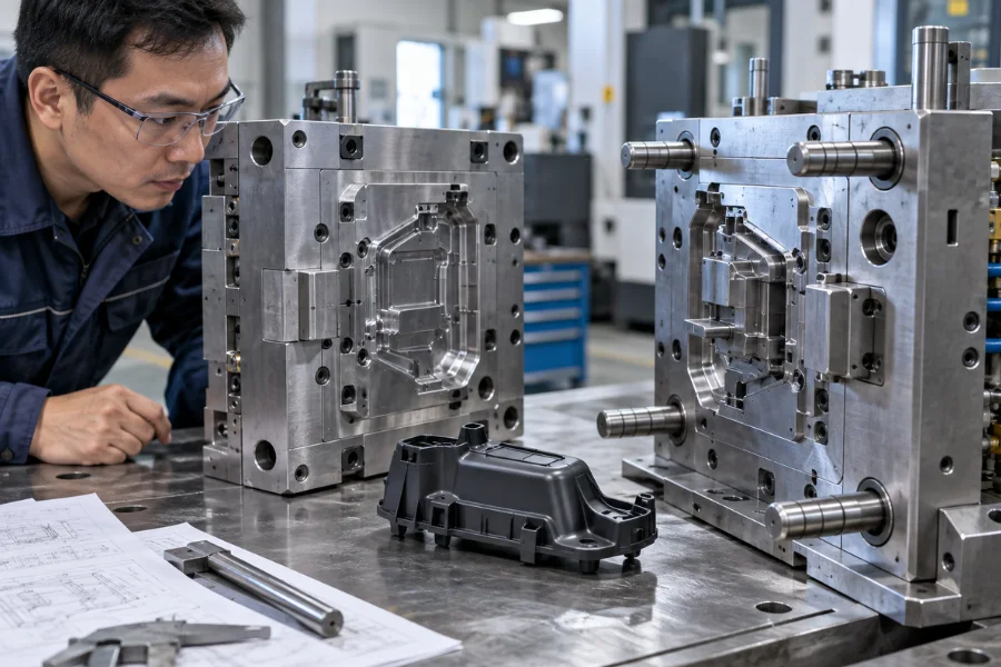
A mold can produce an acceptable part during an initial trial and still perform poorly in production. Uneven cooling, unstable ejection, trapped air, mold deflection, or difficult maintenance may only become apparent after repeated cycles.
Injection mold design goes beyond machining a cavity that matches the part CAD. The mold must manage melt flow, air evacuation, heat removal, shrinkage, part release, and structural loads within the same production system. A successful design should produce acceptable parts repeatedly while meeting dimensional, cycle-time, maintenance, and tool-life requirements.
Injection mold design is the engineering process of defining the structure and functional systems of a mold used to manufacture plastic parts by injection molding.
It converts part requirements into a production system:
Part Geometry → Mold Structure → Melt Flow → Cooling and Shrinkage → Part Release → Repeatable Production
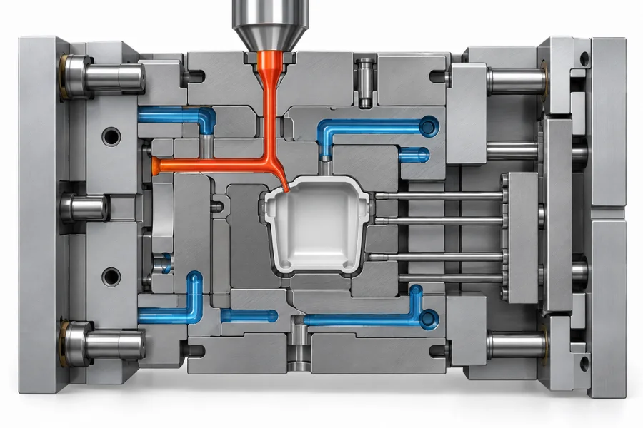
A typical injection mold performs several functions simultaneously:
| Mold Function | Engineering Objective |
|---|---|
| Core and cavity | Form the internal and external part geometry |
| Feed system | Deliver molten resin into the cavity |
| Venting | Allow displaced air and gases to escape |
| Cooling | Remove heat and control solidification |
| Ejection | Release the molded part without damage |
| Alignment and support | Maintain mold position and resist molding forces |
A decision in one area can change requirements elsewhere. Gate placement affects filling and packing, cooling influences shrinkage and release conditions, and the parting line can affect both venting and flash control.
Plastic injection mold design starts with the part because its geometry establishes many of the tooling constraints.
Nonuniform wall thickness changes filling, packing, and cooling behavior. Thick regions may require more effective packing and heat removal, influencing gate location and cooling-channel layout.
Draft affects how readily the cooled part releases from cores and cavity surfaces. The required draft depends on material, surface texture, feature depth, and mold construction rather than a single universal angle.
Ribs and bosses introduce local geometry that can affect shrinkage and cooling. Undercuts have a more direct tooling consequence because features that cannot release along the primary opening direction may require sliders, lifters, collapsible cores, removable inserts, or other side actions.
The practical DFM question is not simply whether the geometry can be molded. It is whether the part can be filled, cooled, and released with a mold that remains stable and maintainable throughout the intended production run.
Mold architecture should follow production requirements rather than tooling complexity alone. Production volume, part geometry, resin behavior, required output, automation, and machine constraints all influence the configuration.
A single-cavity mold generally offers simpler manufacturing and maintenance. Multi-cavity tooling increases output per cycle but introduces additional demands for balanced filling, consistent cooling, cavity-to-cavity dimensional control, and machine capacity.
Plate and feed-system configurations add another decision layer. Two-plate molds provide relatively straightforward construction, while three-plate designs can offer additional gate-placement flexibility. Cold runners simplify the feed system but create runner material, whereas hot runners can reduce this waste and provide greater gating flexibility at the expense of higher tooling complexity, temperature control, and maintenance requirements.
Stack molds, two-shot tooling, insert molding tools, and other specialized structures become relevant when the product or production strategy requires additional cavity levels, materials, inserts, or mold movements.
The appropriate architecture is the one that achieves the required output and part quality without introducing unnecessary tooling risk.
The parting line defines where the mold separates. Its location affects mold construction, flash risk, surface appearance, machining, venting, and the direction in which the part can be released.
A practical parting line should support reliable mold opening while keeping witness lines and potential flash away from critical cosmetic, sealing, or functional surfaces. Complex geometries may also require shut-off surfaces capable of maintaining reliable contact under repeated molding loads.
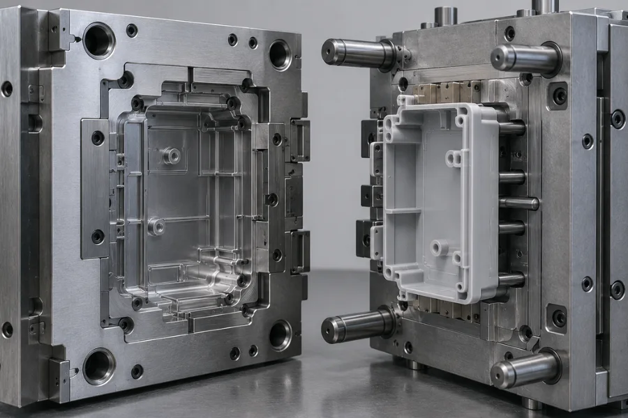
In many conventional mold layouts, the part is intentionally retained on the moving half—often the core side—so the ejector system can remove it after mold opening.
Shrinkage around the core can help create this retention, but core/cavity allocation must also account for cosmetic surfaces, deep features, undercuts, dimensional requirements, and available ejector locations.
Excessive retention raises ejection force and the risk of deformation or drag marks. Insufficient or poorly controlled retention can cause the part to remain on the wrong side of the mold or release unpredictably.
Alignment and structural support are equally important. Guide pins, bushings, interlocks, and supporting components maintain the relationship between mold halves, while the cavity region must withstand molding loads without excessive deflection. Poor support or inadequate shut-offs can contribute to flash, dimensional variation, and accelerated wear.
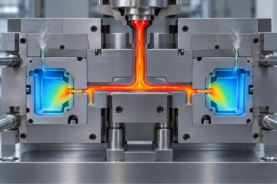
The feed system carries molten resin from the machine nozzle into the mold cavity. In a conventional cold-runner mold, the flow path is:
Sprue → Runner → Gate → Cavity
Runner dimensions balance pressure loss, material volume, and stable melt delivery. Multi-cavity molds add the requirement of distributing material consistently between cavities.
Common gate configurations include edge, pin, submarine, fan, hot-tip, and valve gates. The gate type affects mold construction and gate removal, but its location often has a greater influence on molding behavior.
Gate location can affect:
Gate size also influences how long packing pressure can remain effective. Once the gate freezes, additional holding pressure can no longer compensate for volumetric shrinkage through that flow path. Gate dimensions therefore affect packing behavior as well as filling.
In multi-cavity tooling, equal cavity count does not guarantee balanced filling. Runner length, pressure drop, cavity geometry, and thermal conditions must all be considered.
The final feed-system layout also has to coexist with cooling channels, ejectors, inserts, and side actions. A favorable gate location on a flow simulation may need adjustment if it creates an impractical tooling arrangement.
The cavity contains air before every shot. As molten plastic advances, that air needs a controlled escape path.
Vents are commonly placed near end-of-fill regions, parting surfaces, deep features, inserts, and locations where converging flow fronts may trap gas. Depending on the mold construction, clearances around certain ejector components can also contribute to gas evacuation.
Vent geometry involves a practical balance. The vent must provide enough flow area for air and gases to escape without allowing the polymer melt to produce unacceptable flash. Suitable dimensions depend on the resin, processing conditions, and mold configuration.
Poor venting can contribute to burn marks, incomplete filling, gas traps, and weak weld regions. Raising injection pressure will not correct an air trap if the displaced gas has no effective exit path.
Vent locations should therefore follow the expected filling pattern. Moving the gate can change the final filling region and, with it, the areas where venting is most important.
Cooling design is a heat-balance problem, not simply a cycle-time problem.
Cooling channels must remove enough heat for safe part release while limiting temperature differences across the molded component. Channel location, spacing, coolant flow, mold material, cavity geometry, and local part thickness all influence thermal performance.
Deep cores and thick regions are particularly difficult to cool because heat may have a longer conduction path to conventional drilled channels. Bubblers, baffles, high-conductivity inserts, or conformal cooling may be considered when standard channels cannot provide adequate temperature control.
The practical target is to cool the part quickly and uniformly. Uneven mold temperatures produce different solidification and shrinkage behavior across the component, increasing the risk of warpage and dimensional variation.
Feed-system geometry can also create localized thermal loads, while the temperature distribution at mold opening affects how stiff the part is during ejection. Cooling layout should be evaluated alongside part geometry, gate location, shrinkage behavior, and release requirements.
After the part reaches a suitable release condition, it must leave the mold without excessive deformation, scratching, or other surface damage.
Plastic contracts during cooling and often grips the core. Draft, core geometry, surface texture, material shrinkage, and part temperature all influence the required release force.
Common ejection methods include ejector pins, sleeves, blades, stripper plates, and air-assisted mechanisms. Selection depends on the geometry and the areas available to support the part during release.
Force distribution is often more important than simply increasing ejector force. Ejectors should act on sufficiently strong areas and avoid concentrating loads on thin walls or critical cosmetic surfaces.
Timing also matters. Ejecting while the part is too hot can allow pins or other ejectors to deform insufficiently stiff sections, while unnecessarily extending cooling increases cycle time.
Ejector marks, cracking, deformation, drag marks, or sticking should prompt a review of draft, surface condition, core retention, cooling, and ejector placement before ejection force alone is increased.
Tool materials should be selected according to the mechanical, thermal, surface, and lifecycle requirements of the components they serve.
Important considerations include expected shot volume, resin abrasiveness, corrosion, operating temperature, surface-finish requirements, machinability, wear resistance, repairability, and maintenance strategy.
| Mold Material | Typical Design Consideration |
|---|---|
| Aluminum | Prototype and lower-volume tooling |
| P20 steel | General-purpose production tooling |
| H13 steel | Components exposed to greater wear or thermal demands |
| Stainless mold steel | Corrosion-sensitive or demanding polish applications |
These are representative applications rather than universal material-selection rules.
A production mold also does not necessarily use one material throughout. Mold bases, cavity and core inserts, wear components, gates, and ejector elements may use different materials according to their functions.
Abrasive filled resins, for example, can justify greater wear resistance around gates and molding surfaces. Corrosive materials or operating environments may require corrosion-resistant steels or protective treatments.
Tool steel should ultimately be evaluated against expected production life and maintenance requirements, not initial material price alone.
Mold flow simulation can identify potential risks before tool manufacturing by modeling how the selected resin is expected to behave in the proposed cavity and feed system.
Depending on the analysis, engineers can evaluate:
The results can guide gate position, runner dimensions, cavity balance, venting, and cooling decisions before expensive tooling changes are required.
Simulation is particularly useful for complex geometries, long or thin flow paths, multi-cavity tools, fiber-filled materials, and components with demanding dimensional requirements.
It remains a risk-reduction and design-optimization method rather than proof of production readiness. Prediction quality depends on material data, process assumptions, boundary conditions, and the accuracy of the modeled geometry.
Physical mold trials are still needed to evaluate the complete interaction between the tool, resin, molding machine, and process.
After design release, mold components are manufactured using processes such as CNC machining, EDM, grinding, drilling, and polishing before assembly and trial molding.
Initial trials evaluate filling, flash, short shots, venting, ejection, appearance, dimensions, warpage, and cycle behavior. Trial data is then compared with the design assumptions so that controlled tooling or process adjustments can be made.
Where appropriate, critical mold features can be designed steel-safe, leaving material available for controlled dimensional adjustment after trial measurements. This can reduce the need for welding or component replacement when corrections are required.
The development sequence is:
Design → Manufacturing → Assembly → Mold Trial → Measurement → Correction → Validation
Not every molding defect originates in the tool. Material preparation, machine capability, and process settings can also contribute, but recurring problems should be checked against the relevant mold systems.
| Production Problem | Mold Design Areas to Review |
|---|---|
| Short shot | Gate, runner resistance, venting |
| Flash | Parting surfaces, alignment, structural support |
| Burn marks | Venting and end-of-fill regions |
| Warpage | Cooling balance, gate location, cavity layout |
| Sink marks | Local thickness, packing path, cooling |
| Part sticking | Draft, core geometry, surface condition |
| Ejector marks | Ejector position and force distribution |
Warpage illustrates why the distinction matters. Increasing holding pressure may change the result, but it cannot necessarily correct uneven cooling, unbalanced filling, or geometry-driven shrinkage.
Troubleshooting should distinguish between a process-sensitive problem and a design-limited problem before permanent tooling changes are made.
Injection mold design affects both the initial tooling investment and the cost of every acceptable part produced afterward.
Cavity count, mold steel, hot runners, sliders, lifters, advanced cooling, surface requirements, and automation can increase upfront cost. During production, cycle time, scrap, runner waste, maintenance, downtime, cavity output, and tool life determine whether that investment is economical.
A more capable cooling system may justify its additional tooling cost if it shortens cycle time while maintaining dimensional stability over a high production volume. More durable mold materials can likewise reduce maintenance when processing abrasive resins.
The lowest quoted tooling price does not necessarily produce the lowest cost per acceptable part.
Before releasing the mold design for manufacturing, the engineering review should confirm that:
A design review cannot eliminate every correction during tool trials, but it can prevent many avoidable changes after the mold has already been manufactured.
Engineers typically need the part geometry, selected or proposed resin, expected production volume, dimensional requirements, surface requirements, assembly or functional constraints, and relevant molding-machine or tooling limitations. Unresolved requirements at this stage can lead to significant tooling changes later.
Gate location should support stable filling and packing while accounting for flow length, weld lines, air traps, material orientation, warpage, gate vestige, and cosmetic requirements. Complex filling patterns may justify mold flow analysis before the location is finalized.
Cooling affects cycle time, shrinkage, dimensional stability, and the condition of the part during ejection. The cooling system should remove heat efficiently without creating excessive temperature differences across the molded component.
Mold flow analysis is particularly useful for complex parts, long or thin flow paths, multi-cavity molds, fiber-filled materials, difficult gate decisions, or demanding dimensional requirements. Its predictions still need to be evaluated against actual mold trials.
A production-ready injection mold should be judged by repeatability rather than whether it can produce an acceptable first part. Filling, venting, cooling, ejection, structural support, and maintenance all have to operate within a practical manufacturing window.
The most effective injection mold design is not necessarily the most complex tool. It is one that can reliably fill, cool, release, and repeat while meeting the required part quality, production volume, tool life, and manufacturing cost.