Physical Address
304 North Cardinal St.
Dorchester Center, MA 02124
Physical Address
304 North Cardinal St.
Dorchester Center, MA 02124
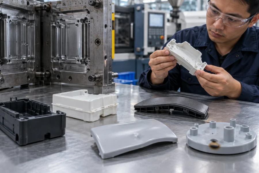
Injection molding defects rarely come from one machine setting alone. A short shot may result from insufficient injection pressure, but the same symptom can also point to a restrictive gate, trapped air, excessive flow length, low melt temperature, or inconsistent machine delivery.
Effective troubleshooting starts by identifying the physical mechanism behind the defect before changing process parameters. The key question is whether the problem originates in the material, process, equipment, mold, or part geometry—and whether it can be corrected without creating another quality problem.
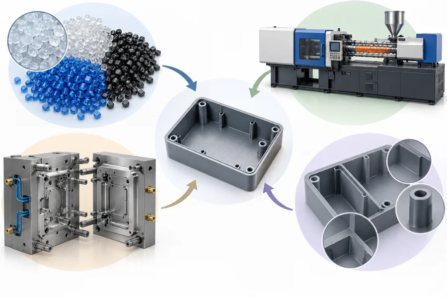
Most molding defects develop through interactions among material behavior, processing conditions, part geometry, mold design, and equipment performance. The visible defect therefore does not always reveal its root cause.
| Root Cause | Variables to Check | Commonly Associated Defects |
|---|---|---|
| Material | Moisture, contamination, viscosity, degradation | Splay, bubbles, delamination, discoloration |
| Process | Melt/mold temperature, injection speed, pressure, packing, cooling | Short shots, flash, sink marks, burn marks |
| Part design | Wall thickness, ribs, bosses, flow length, geometry | Sink marks, voids, warpage, weld lines |
| Mold design | Gates, runners, venting, cooling, parting line | Short shots, burns, flash, jetting |
| Equipment | Check ring, clamp, dryer, temperature control | Short shots, flash, inconsistent filling |
These categories overlap. Higher injection pressure, for example, may fill a restrictive cavity while increasing the risk of flash or residual stress.
The objective is a stable processing window—a range of conditions that can repeatedly produce acceptable parts despite normal variation in material and machine performance—not a single narrowly tuned setting.
Before adjusting the machine, confirm that production is operating from a known baseline. Otherwise, parameter changes can mask a material, equipment, or maintenance problem.
Check the following first:
Contamination, improper drying, restricted vents, cooling problems, or machine wear can produce symptoms that resemble process-setting problems. Once these baseline conditions are stable, change one relevant variable at a time where practical and observe the response.
A short shot occurs when molten plastic fails to completely fill the cavity. The melt may lose pressure, temperature, or flow capability before reaching the end of fill, or trapped air may resist the advancing flow front.
Possible process causes include insufficient shot size, low injection pressure, low injection speed, and low melt temperature. Small gates or runners, long flow paths, inadequate venting, and thin sections can create additional resistance. A worn check ring can produce similar symptoms by reducing actual material delivery.
Start with shot size, cushion consistency, machine performance, and material condition. If these are stable, evaluate the response to individual changes in injection speed, pressure, or thermal conditions rather than increasing several variables at once.
If a modest adjustment produces a complete and repeatable fill, the issue may be process-related. If filling consistently requires unusually aggressive conditions, inspect venting, gate and runner dimensions, flow length, and wall thickness rather than continuing to increase machine settings.
Flash is excess plastic that escapes the intended cavity, commonly along the parting line, shutoffs, ejector areas, or vents.
Excessive cavity pressure, high injection speed, a low-viscosity melt condition, or insufficient clamp force can promote flash. Damaged parting surfaces, mold mismatch, wear, contamination at shutoffs, or unsuitable vent dimensions can create the same visible defect.
The interaction between flash and filling provides an important diagnostic clue. Lowering injection pressure may reduce flash, but it is not a robust correction if the same adjustment immediately creates a short shot.
When acceptable filling and flash control cannot be achieved within a reasonable processing window, inspect the parting line, shutoffs, mold condition, venting, flow resistance, and clamp requirements.
Sink marks are localized depressions that commonly appear opposite thick walls, ribs, bosses, or other areas with concentrated material.
The surface of a molded part solidifies before its core. As the hotter internal material continues to cool, volumetric shrinkage occurs. If additional material cannot adequately compensate for this shrinkage before the gate freezes, the surface may be pulled inward.
Insufficient pack/hold pressure or time can contribute, but excessive section thickness, premature gate freeze, gate location, and uneven cooling may also limit compensation.
The response to packing is useful during diagnosis. If reasonable changes to pack/hold conditions clearly reduce the sink, packing and gate-freeze behavior deserve further investigation. If the depression remains directly over the same thick rib, boss, or transition, part geometry is more likely contributing to the problem.
Reducing unnecessary material concentration and maintaining more uniform wall thickness generally provides a more robust DFM solution. Rib thickness is commonly kept below the adjacent nominal wall thickness; guidelines around 40%–60% are often used as a starting point for some designs, but the final ratio should reflect the resin, geometry, structural requirements, and cosmetic expectations.
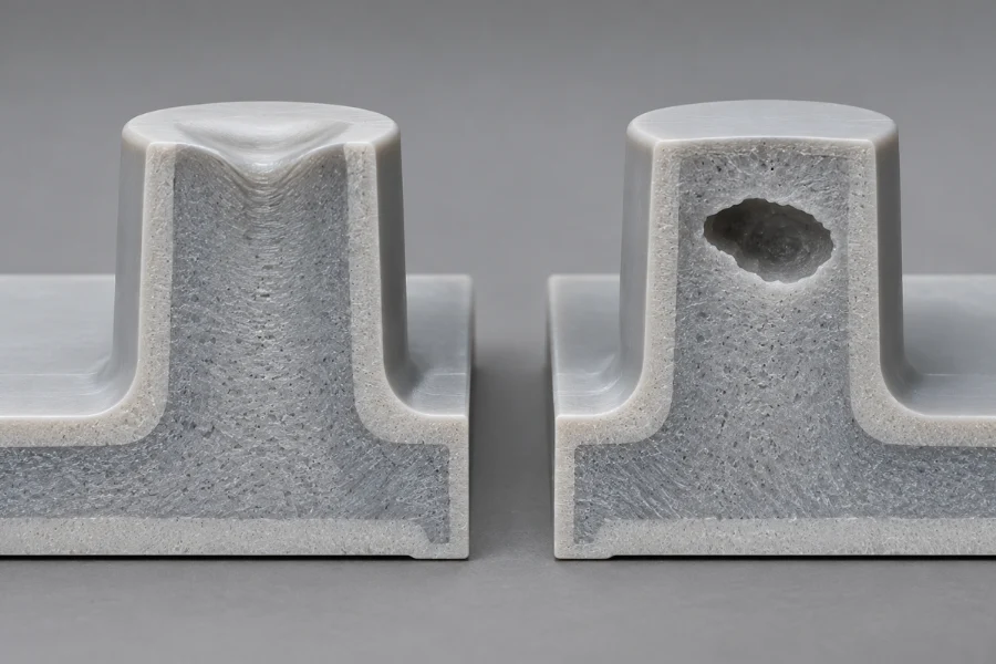
An internal cavity does not automatically indicate trapped air. Vacuum voids and gas or moisture bubbles can look similar while forming through different mechanisms.
A vacuum void can develop in a thick section as the internal material cools and contracts after the surrounding skin has solidified. If sufficient material cannot compensate for this shrinkage, the resulting volume loss may appear internally rather than as a visible surface depression.
Sink marks and vacuum voids can therefore arise from related shrinkage and packing limitations, although where and how the shrinkage manifests differs. Thick sections, gate-freeze behavior, packing conditions, and thermal conditions should all be considered.
A gas or moisture bubble follows a different diagnostic path. Moisture, volatile contamination, material degradation, or gas carried into the melt can create internal bubbles.
For suspected bubbles, verify resin drying and material preparation first. For shrinkage-related voids, investigate section thickness and packing behavior. Improving mold venting alone will not necessarily correct an internal void caused by volumetric shrinkage.
Warpage occurs when different regions of a molded part shrink by different amounts or in different directions, leaving the part bowed, twisted, or dimensionally distorted.
Cooling imbalance is a common cause, but simply extending cooling time does not always address the mechanism. Compare mold temperatures, coolant flow, cooling-channel placement, wall thickness, packing behavior, and the thermal mass of different regions.
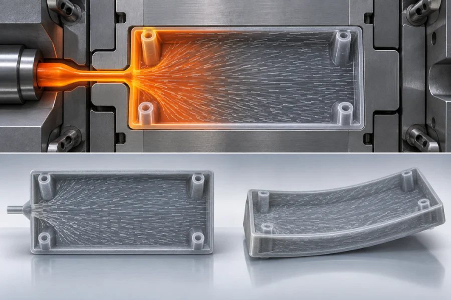
Material structure also matters. In fiber-filled polymers, melt flow influences fiber orientation, and orientation can produce directional shrinkage:
Gate Location → Flow Direction → Fiber Orientation → Anisotropic Shrinkage → Warpage
Changing the gate or filling pattern can therefore alter warpage even when nominal cooling conditions remain similar.
If distortion develops mainly after ejection, cooling and ejection conditions deserve attention. If the same regions consistently distort despite adequate cooling, investigate part geometry, mold thermal balance, gate location, and material shrinkage behavior.
Weld or knit lines form where separate melt fronts meet after flowing around holes, inserts, core features, or through multi-gate filling patterns.
The line becomes more pronounced when the approaching fronts have cooled, lost pressure, or trapped gas at the meeting point. In structurally loaded regions, poor bonding can also create a local mechanical weakness rather than a purely cosmetic defect.
If the weld improves when the flow fronts arrive hotter or with better pressure transfer, premature cooling or filling conditions may be involved. Melt and mold temperature, injection speed, pressure, and venting can then be evaluated within the material’s recommended processing range.
Some geometries inevitably create split-and-rejoin flow. When the weld line cannot be eliminated, relocating it to a lower-stress region through gate or flow-path changes may be more effective than continually increasing temperature or pressure.
Burn marks often appear as brown, dark, or black areas near the end of fill, but similar discoloration can originate from different mechanisms.
One common mechanism is trapped-air compression. Incoming melt rapidly compresses an air pocket that cannot escape, generating localized heat. A burn that repeatedly appears at the same flow-end or dead-end location is a strong reason to investigate air traps and venting.
Material degradation can create similar marks through excessive melt temperature, high screw speed, prolonged thermal exposure, or high shear through restrictive nozzles, runners, gates, or thin sections.
Location and repeatability are therefore useful diagnostic evidence rather than proof of a single cause. Consistent end-of-fill burns point toward venting and flow behavior, while less localized dark streaking may justify checking material thermal history, barrel cleanliness, screw conditions, and residence conditions.
Flow lines are visible streaks, waves, or patterns created as the melt flows and solidifies unevenly across the cavity surface.
Low melt temperature, low mold temperature, or slow filling can allow the advancing flow front to cool prematurely. Abrupt wall-thickness transitions, restrictive gates, and changes in flow direction can also create local differences in flow velocity and surface solidification.
If the defect responds consistently to filling speed or thermal conditions, process optimization may be sufficient. If the pattern remains tied to the same thickness transition or flow restriction, geometry or gate design should be reviewed.
Flow lines are often cosmetic, but they can also indicate unstable filling behavior. The goal is a stable flow front rather than simply making the surface pattern less visible.
Jetting typically appears as a snake-like or worm-like line extending from the gate. It occurs when melt enters an open cavity as a high-velocity free jet instead of immediately contacting and spreading along the cavity wall.
Initial injection speed, gate size, mold temperature, and gate orientation can influence this behavior. A small gate directed into a large open cavity may remain sensitive to jetting even after process adjustments.
Reducing initial filling speed can help determine whether velocity is driving the defect. If jetting persists across a reasonable process range, examine gate geometry and orientation.
Where geometry permits, directing the incoming melt toward a cavity wall or core can encourage progressive wall-controlled filling. This can be more robust than permanently slowing the entire injection profile to compensate for an unfavorable gate entry condition.
Several surface defects should trigger a review of material condition and thermal history before major tooling changes are considered.
Splay or silver streaks may result from moisture, excessive shear, high screw speed, restrictive gates, or material degradation. Confirm drying requirements and material condition rather than assuming every silver streak originates in the mold.
Surface delamination appears as thin layers peeling or separating from the molded surface. Contamination, incompatible polymers, excessive mold-release agent, or material incompatibility should be investigated first.
Discoloration may result from degraded resin, residual material from a previous run, contamination, unstable colorants, or excessive thermal exposure. Purging, material handling, barrel conditions, processing temperature, and material residence history are useful diagnostic checks.
The common point is that a surface abnormality does not automatically justify modifying the mold. Material preparation and processing history may provide the faster route to the root cause.
Once the defect is identified and the baseline confirmed, troubleshooting should progressively narrow the cause rather than introduce more variables.
This sequence helps distinguish a correctable process deviation from a more persistent tooling or part-design limitation.
The most reliable defect prevention begins before repeated machine adjustments become necessary.
During part DFM, review wall-thickness transitions, ribs, bosses, long flow lengths, potential air traps, weld-line locations, draft, and areas with concentrated thermal mass. These features influence how the material fills, packs, cools, shrinks, and ejects.
Mold design should support the geometry through appropriate gates, runners, venting, cooling, and ejection. Gate placement affects more than filling distance; it can also influence packing efficiency, weld-line position, flow orientation, and warpage.
Material preparation should follow the requirements of the selected resin grade, particularly for drying, contamination control, allowable regrind, and processing conditions.
Finally, mold trials should establish a repeatable processing window rather than a single machine recipe that happens to produce a good part. The process should remain capable as normal production variables change within controlled limits.
Visual and dimensional inspection can identify many molding defects, but internal or thermally driven problems may require additional diagnostic methods.
Thermal measurements can help identify cooling imbalance, while flow simulation can support analysis of filling patterns, weld lines, pressure requirements, and potential air traps. For critical internal voids, sectioning or non-destructive methods such as X-ray or CT may be justified.
These methods support root-cause analysis rather than replace it. Their value depends on accurate material data, process inputs, and correlation with actual molding conditions.
| Defect | Typical Quality Risk | First Check | Likely Process Cause | When to Check Mold / DFM |
|---|---|---|---|---|
| Short shot | Functional / dimensional | Shot and filling consistency | Low speed, pressure, temperature, or shot delivery | Filling repeatedly stops at the same region or requires excessive conditions |
| Flash | Cosmetic / dimensional / assembly | Clamp and cavity pressure | Excessive pressure/speed or low melt viscosity | Flash persists at the same parting line or shutoff |
| Sink marks | Cosmetic / dimensional | Response to pack/hold | Insufficient packing or premature gate freeze | Sink remains over thick ribs, bosses, or wall transitions |
| Voids | Structural / internal quality | Determine void type | Insufficient packing or material/gas issue | Vacuum void remains concentrated in thick sections |
| Warpage | Dimensional / assembly | Cooling and ejection behavior | Cooling or packing imbalance | Distortion follows geometry, cooling layout, or flow orientation |
| Weld lines | Cosmetic / potentially structural | Flow-front condition | Premature cooling, pressure loss, or trapped gas | Weld remains in a critical location because of gate or part geometry |
| Burn marks | Cosmetic / potential material degradation | Location and repeatability | Trapped gas, excessive speed, or thermal degradation | Burn repeatedly occurs at a flow-end air trap |
| Flow lines | Mainly cosmetic | Filling stability | Low speed or unfavorable thermal condition | Pattern follows a thickness transition or restrictive flow path |
| Jetting | Cosmetic / local quality | Initial gate flow | Excessive initial injection speed | Defect persists because of gate size, direction, or cavity entry |
| Splay | Cosmetic / possible material condition | Resin condition | Moisture, degradation, or excessive shear | Gate restriction contributes excessive shear |
The severity of any defect ultimately depends on the part and application. A weld line on a non-critical cosmetic surface, for example, carries a different manufacturing risk from the same weld line across a highly loaded feature.
The first question in injection molding defect troubleshooting should not be, “Which machine setting should we change?” It should be, “What physical mechanism produced this defect?”
Process optimization can correct many molding problems, but it should not be used indefinitely to compensate for inadequate venting, unbalanced cooling, restrictive flow paths, damaged tooling, or unfavorable part geometry.
Stable production comes from aligning material behavior, part design, mold design, and processing conditions so acceptable parts can be produced across a repeatable processing window—not only at one narrowly tuned machine setting.