Physical Address
304 North Cardinal St.
Dorchester Center, MA 02124
Physical Address
304 North Cardinal St.
Dorchester Center, MA 02124

For many smooth injection molded surfaces, 1° to 2° of draft per side is a practical starting point. Deep features, textured surfaces, and internal walls that shrink tightly around mold cores may require different angles.
The correct draft angle depends on material shrinkage, feature geometry, surface finish, ejection conditions, and dimensional requirements. Engineers must balance reliable mold release with the geometry needed for assembly and function.
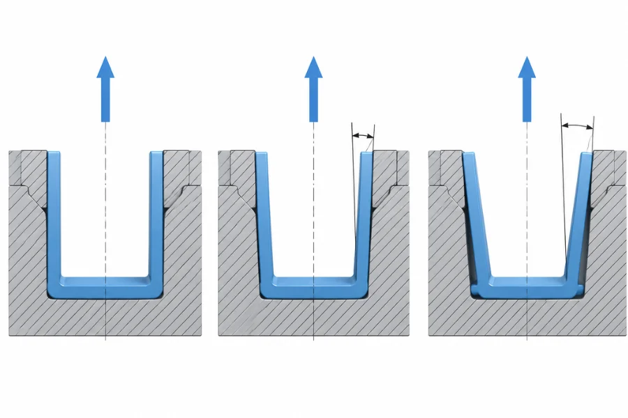
A draft angle is the angle between a molded surface and the direction of mold opening or core withdrawal. It creates clearance as the plastic part moves away from the mold, reducing sliding contact during release.
A surface parallel to the pull direction has 0° draft. Positive draft facilitates straight withdrawal, while negative draft can create an undercut that requires a change in geometry or a movable tooling mechanism.
As plastic cools, shrinkage can cause internal surfaces to grip mold cores, creating contact pressure and friction during ejection. External surfaces may shrink away from cavity walls, although local geometry and processing conditions can maintain contact.
Draft allows clearance to develop as the part moves along the release direction. Insufficient draft can contribute to:
Ejection resistance depends on contact pressure, contact area, friction, and the part’s condition at ejection temperature. Increasing draft can reduce sliding contact as the part moves away from a core, but it does not guarantee lower ejection force under every condition.
Material behavior, surface texture, core geometry, and ejector placement must also be considered. Draft cannot compensate for inadequate ejection support or unsuitable cooling and packing conditions.
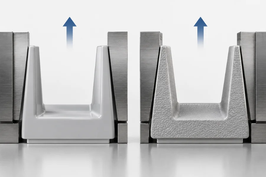
The following values are preliminary design references for conventional injection molding, not universal minimum requirements.
| Design condition | Preliminary draft angle | Key consideration |
|---|---|---|
| Smooth external walls | 1°–2° per side | Common starting range |
| Smooth internal walls | 1°–2° per side | Core grip may require additional draft |
| Short, dimensionally restricted features | 0.25°–0.5° per side | Requires careful release evaluation |
| Deep walls and cavities | Often 2° or more | Contact length and friction influence the requirement |
| Lightly textured surfaces | Around 3° | Depends on texture specification |
| Deeply textured surfaces | 5° or more in some applications | Confirm against texture depth and mold finish |
A shallow, polished feature may release with less draft than a deeper or textured feature. The final angle must be evaluated against the resin grade, part geometry, surface specification, and ejection method.
Mold shutoff surfaces are metal-to-metal contact regions designed to close openings or form features. Their angles depend on relative mold movement, contact conditions, and tooling requirements.
Some manufacturing guidelines use approximately 3° or greater for angled shutoffs, but this is not a universal requirement. Shutoff geometry should be established by the mold designer rather than inferred from ordinary plastic wall draft recommendations.
Semi-crystalline thermoplastics such as polypropylene (PP) and polyethylene (PE) can exhibit relatively substantial molding shrinkage, depending on grade, geometry, and processing conditions. When a part shrinks around an internal core, the resulting contact pressure may increase friction during ejection.
Amorphous materials such as polycarbonate (PC) and ABS exhibit different shrinkage behavior, but they still require suitable draft. Material shrinkage alone cannot determine the correct angle.
Engineers should evaluate material shrinkage, stiffness at ejection temperature, contact area, surface finish, wall thickness, and ejector placement together. Supplier data supports preliminary decisions, while tooling validation confirms actual release behavior.
Deep walls and long cores can maintain contact with the molded plastic over a greater distance during ejection. This may increase friction and the risk of drag marks, particularly when the part shrinks tightly around the core.
Additional draft can reduce continued sliding contact, but feature depth does not translate into a fixed additional angle. A deep polished feature may release more easily than a shallower feature with substantial texture or core grip.
Polished surfaces generally have fewer surface irregularities than heavily textured surfaces. Mold textures can create small recesses and projections that resist sliding, particularly when the texture is deep.
Additional draft helps the molded surface clear these features during release. The required angle depends on texture depth, pattern, resin, and feature geometry. Confirm the draft requirement against the specified mold texture before tooling begins.
Internal surfaces may shrink tightly around cores, while external surfaces may contract away from cavity walls. This difference can make deep holes, hollow enclosures, and cylindrical bosses more challenging to release.
Internal surfaces do not automatically require a fixed additional angle. Their draft must be evaluated alongside contact length, material shrinkage, mold opening sequence, and the intended ejection direction.
Enclosures generally require draft on both internal and external walls. The relationship between the two angles determines how the wall thickness changes along the feature height.
For opposing planar walls, matching draft angles and compatible taper directions can maintain a constant wall separation along the selected measurement direction. Different angles or taper directions can cause wall thickness to vary with height.
When uniform wall thickness is important, evaluate both surfaces together and verify the resulting geometry in CAD.
Ribs require draft to release from the mold, but increasing draft also reduces the upper width when the base width and height remain fixed.
Consider a rib with a 2 mm base width and a 10 mm height. With symmetrical inward draft, the approximate top width is calculated as follows.
Top width formula
W_top = W_base − 2 × H × tan(α)
Where:
At 1° draft
W_top = 2 − 2 × 10 × tan(1°)
W_top ≈ 1.65 mm
At 2° draft
W_top = 2 − 2 × 10 × tan(2°)
W_top ≈ 1.30 mm
This example illustrates the geometric effect of draft, not a recommended rib proportion. Actual rib dimensions must also satisfy wall thickness, filling, structural strength, and moldability requirements.
Bosses require similar coordination between outer-wall draft and the internal hole. The resulting wall thickness must support the intended fastening or assembly function, while thick sections near the base should be reviewed for sink-mark risk.
Deep holes formed by mold pins may require draft to reduce resistance during core withdrawal. Precision locating holes and functional openings, however, may need tighter dimensional control than ordinary clearance holes.
Raised or recessed text also requires attention to sidewall draft. Narrow strokes and deep engraving can increase release resistance or create fragile mold features. Evaluate text height, stroke width, engraving depth, and surface finish together.
Features that cannot release along the primary mold opening direction may require side actions or other tooling arrangements.
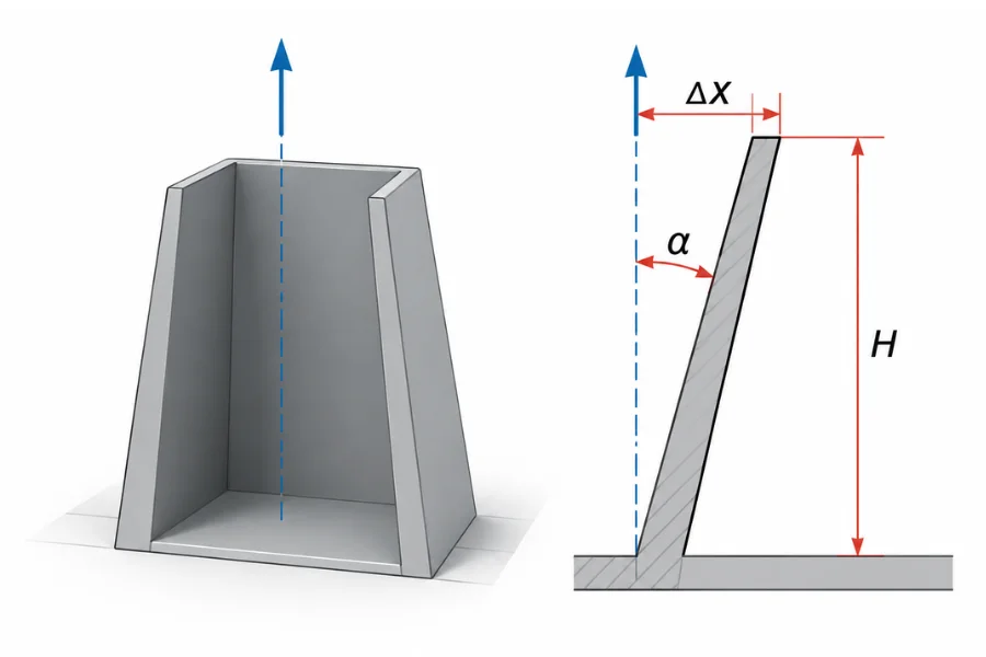
For a straight wall with a constant draft angle, the horizontal offset on one side is calculated as follows.
Single-side offset formula
Δx = H × tan(α)
Where:
For a 40 mm-high wall with 2° draft:
Δx = 40 × tan(2°)
Δx ≈ 1.40 mm
The horizontal offset on one side is approximately 1.40 mm.
For two opposing walls with symmetrical 2° draft, the total width difference is calculated as follows.
Total width difference formula
ΔW = 2 × H × tan(α)
Calculation example
ΔW = 2 × 40 × tan(2°)
ΔW ≈ 2.79 mm
This is the difference between the widths at the two ends of the feature. Whether the upper end is wider or narrower depends on the draft direction and dimensional reference.
If the allowable offset and wall height are known, the corresponding angle is calculated using the inverse tangent function.
Draft angle formula
α = arctan(Δx ÷ H)
For a 30 mm-high wall with an allowable single-side offset of 0.6 mm:
α = arctan(0.6 ÷ 30)
α ≈ 1.15°
This is the maximum angle permitted by the specified geometric offset under the stated assumptions. It does not establish whether the angle is sufficient for reliable ejection.
These equations apply to straight surfaces with constant draft. Curved surfaces and nonuniform tapers require more detailed geometric analysis.
A drafted feature has different dimensions at different positions along its height. A drawing that specifies only one width or diameter may therefore be insufficient to define the geometry needed for assembly.
Consider an enclosure that fits over another component. If its internal walls taper inward toward the closed end, the opening becomes smaller with depth. Measuring the opening alone may not establish clearance at the deepest section.
Engineering drawings should specify:
Where necessary, dimensions should be defined at specified heights or cross-sections. This makes the nominal geometry and functional fit easier to verify.
Yes. If the internal and external walls taper at different angles or in incompatible directions, the distance between them can change along the feature height. This may affect cooling, shrinkage, and local mechanical performance.
When uniform wall thickness is required, coordinate the two surfaces and verify the resulting thickness throughout the part. Draft is part of the nominal geometry and should be accounted for when defining dimensional tolerances.
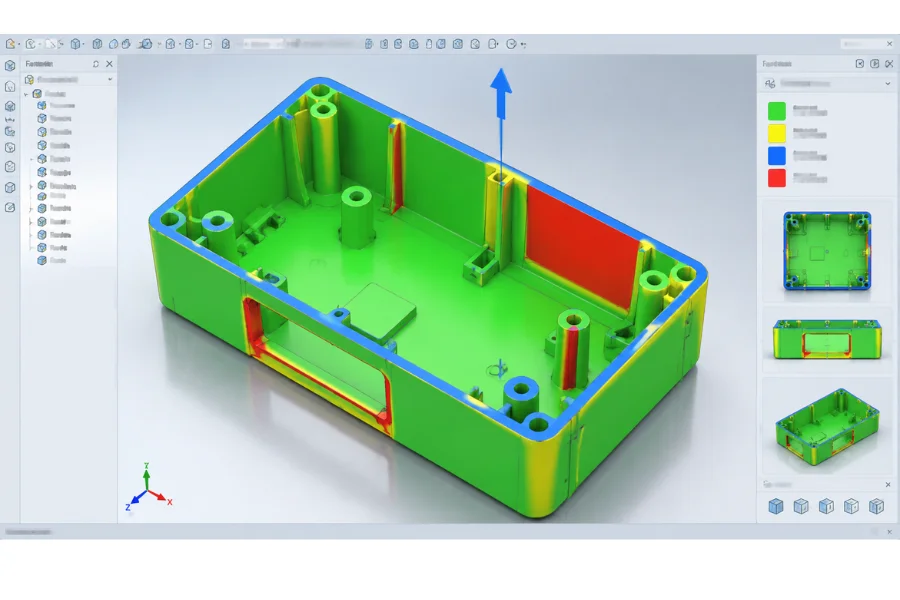
CAD draft analysis identifies surface angles relative to a selected pull direction. It helps engineers locate insufficient draft and negative-draft regions before the mold is built, but it cannot independently confirm successful ejection.
Use this checklist during design review.
Material shrinkage, surface friction, processing conditions, and ejector design must also be evaluated during DFM and tooling validation.
Some components require nearly vertical surfaces to satisfy assembly, appearance, or dimensional requirements. Before accepting limited draft, determine whether the restriction applies to the entire surface or only to a functional contact region.
Possible design responses include:
For some press-fit applications, localized crush ribs can provide interference while allowing the surrounding bore to retain draft. Their dimensions must be evaluated against the mating component, assembly force, material behavior, and molding feasibility.
Zero-draft features are not universally impossible to mold, but their feasibility must be established for the specific geometry and tooling arrangement. Side actions, lifters, or other mechanisms may solve certain release problems, although they add tooling complexity.
There is no universal minimum. Some smooth, shallow features may be produced with 0.5° or less, while deeper or textured features often need more. Material shrinkage, contact length, surface finish, and ejection conditions determine whether a small angle is practical. Confirm the minimum through DFM and molding validation.
A 1° draft angle is a reasonable starting point for many smooth surfaces, especially shallow features. Deep walls, textured surfaces, and internal features that shrink tightly around cores may require more. Evaluate the angle against material behavior, geometry, and the ejection method before finalizing the mold.
Generally, yes. Texture features can increase resistance during mold release, especially when the texture is deep. The required angle depends on texture depth, pattern, resin, and feature geometry. Confirm the final requirement against the mold texture specification.
Specify the draft angle, its direction, and the dimensional references used to control the tapered feature. Define critical dimensions at locations relevant to assembly or function. Where necessary, specify dimensions at particular heights or cross-sections to avoid ambiguity.
Sometimes. If a feature can be redesigned to release along the primary mold opening direction, a side action may no longer be necessary. However, draft cannot eliminate every undercut. Features that mechanically interfere with straight mold opening may still require slides, lifters, or movable cores.
Select draft angles by balancing release resistance with the part’s geometry, surface finish, and dimensional requirements. Verify the resulting dimensions and mold-release conditions during DFM, especially for deep features, textured surfaces, and critical mating interfaces.