Physical Address
304 North Cardinal St.
Dorchester Center, MA 02124
Physical Address
304 North Cardinal St.
Dorchester Center, MA 02124
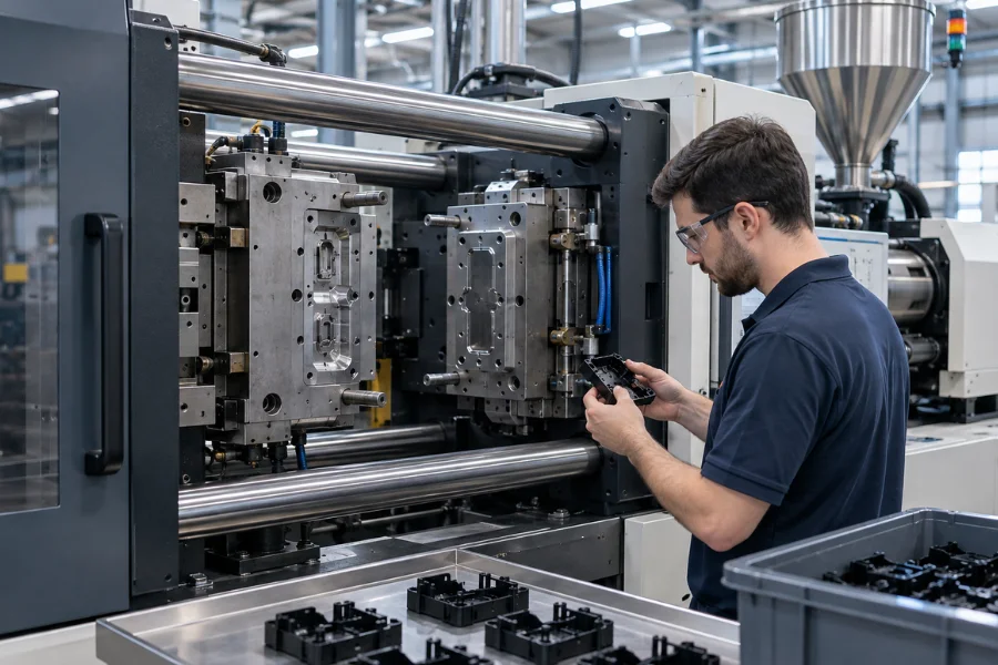
The injection molding process is often described as melting plastic, injecting it into a mold, cooling it, and ejecting the finished part. In production, each stage changes the conditions for the next.
Material preparation affects melt stability, filling determines how pressure develops inside the cavity, packing compensates for shrinkage, and cooling influences dimensions, warpage, and cycle time. Repeatable production depends on controlling the complete molding cycle rather than optimizing one machine setting in isolation.
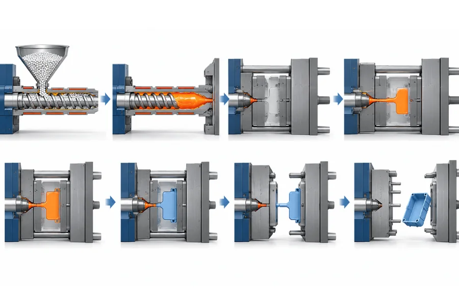
Injection molding converts polymer material, usually supplied as pellets or granules, into a molded part using heat, pressure, and a precision mold.
In a typical reciprocating-screw machine, the resin is plasticized inside the injection unit. The mold closes, molten plastic fills the cavity, pressure is maintained to compensate for cooling shrinkage, and the part remains in the mold until it is rigid enough for ejection.
A typical production sequence is:
Material Preparation → Plasticizing → Mold Closing → Filling → Packing and Holding → Cooling → Mold Opening → Ejection
Three main elements support this cycle: the injection unit, which prepares and delivers the melt; the clamping unit, which opens, closes, and holds the mold; and the mold, which forms the part and controls much of its filling, cooling, and ejection behavior.
These stages are interdependent. A dimensional problem detected after ejection may have originated from resin condition, filling behavior, insufficient packing, part geometry, or uneven cooling earlier in the cycle.
Stable molding begins before the resin enters the barrel.
Raw material should be checked for the correct grade, pellet condition, contamination, color, and any additives required for the application. Colorants, fillers, reinforcements, and other modifiers may also need to be blended with the base resin before processing.
Drying is particularly important for moisture-sensitive polymers. Processing resin with excessive moisture can contribute to surface defects, bubbles, property loss, or material degradation.
Drying requirements depend on the polymer and grade, so temperature and drying time should follow the resin supplier’s recommendations. Storage and handling after drying also matter because some polymers can absorb moisture again before reaching the machine.
When changing resin grades or colors, the barrel may require purging to prevent degraded or incompatible material from contaminating the next production run.
If the material entering the machine is unstable, downstream changes to pressure, speed, or temperature may only mask the underlying problem.
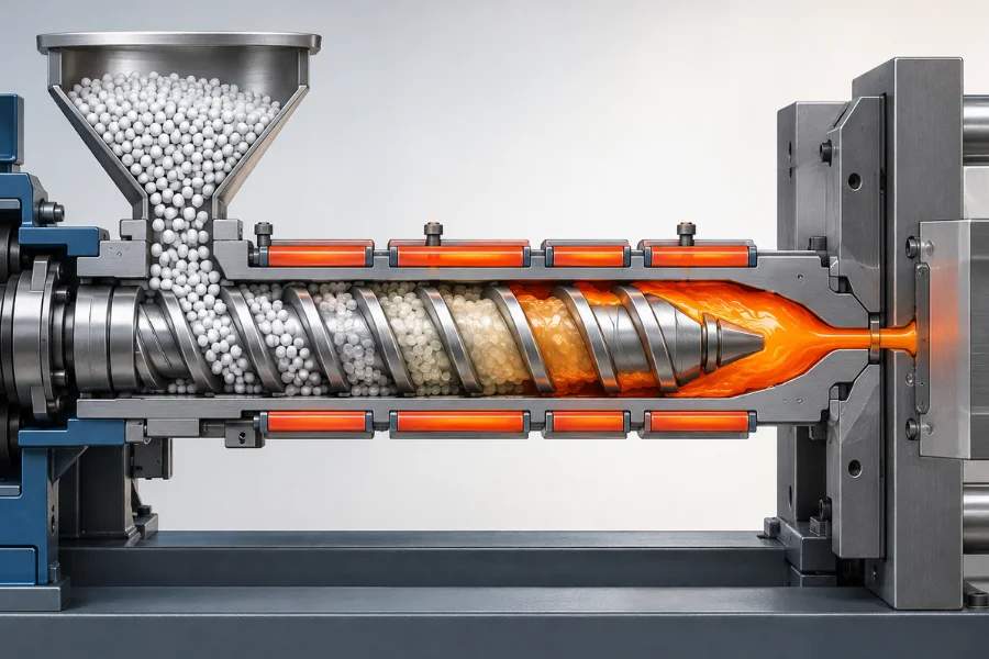
Inside a reciprocating-screw injection molding machine, the screw rotates and transports material forward while the resin changes from solid pellets into a homogeneous melt.
Heater bands provide thermal energy, while screw rotation generates shear and frictional heat and mixes the polymer. The prepared melt accumulates in front of the screw until the required shot is ready for injection.
Important variables include:
Back pressure can improve mixing, temperature uniformity, color dispersion, and melt consistency. Excessive back pressure, however, can increase shear heating, slow plasticizing, and expose thermally sensitive materials to unnecessary heat history.
Barrel temperature involves a similar trade-off. Insufficient heat can result in poor plasticization and high flow resistance, while excessive temperature or residence time can increase the risk of polymer degradation.
The required settings should produce a stable, sufficiently homogeneous melt within the processing window of the selected resin.
Before filling begins, the mold halves close and the clamping unit applies enough force to keep the mold closed during injection and packing.
Pressure inside the cavities acts over the projected area of the part and runner system, creating a force that tends to separate the mold halves. Required clamping force therefore depends on projected area, cavity pressure, cavity count, runner layout, resin behavior, and mold construction.
Too little clamping force can allow the mold to separate slightly and create flash. Excessive force is not automatically safer because it can increase loading on the mold and machine and may compress vents at the parting line.
The objective is sufficient clamping capacity with an appropriate processing margin, rather than simply using the highest available force.
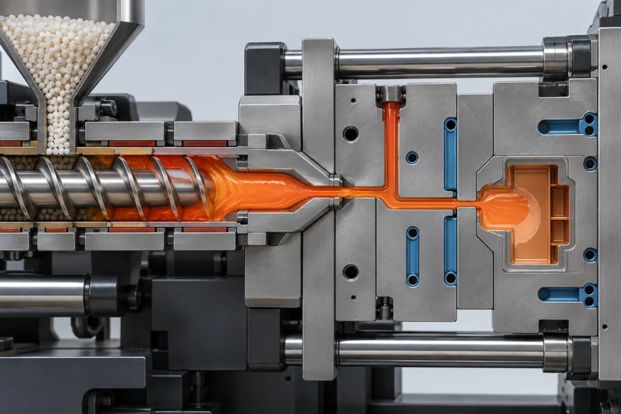
Once the mold is closed, the screw moves forward and forces the prepared melt through the nozzle and into the mold.
In a conventional cold-runner system, the flow path is typically:
Nozzle → Sprue → Runner → Gate → Cavity
The melt must reach the required areas of the cavity before cooling raises its viscosity enough to restrict flow.
Injection speed and pressure are important, but filling behavior also depends on melt temperature, mold temperature, material viscosity, gate design, wall thickness, flow length, and venting.
Thin sections and long flow paths, for example, increase filling difficulty because the melt loses heat while traveling through restrictive geometry. Increasing pressure may not solve a problem caused by an undersized gate, poor venting, or impractical wall thickness.
Gate location also changes how flow fronts move through the cavity, affecting weld-line position, air trapping, cavity pressure distribution, packing, and cosmetic appearance.
Short shots, jetting, flow marks, weld lines, flash, and burn marks can develop during or around filling, but the visible defect alone does not identify its root cause.
A cavity that has finished filling is not yet a dimensionally stable molded part.
As the polymer cools, its volume decreases. Holding pressure allows additional melt to enter the cavity after initial filling and compensate for this shrinkage.
Packing conditions influence part weight, sink marks, internal voids, shrinkage, dimensions, and residual stress. Insufficient pressure or holding time can leave regions under-packed, while excessive packing can increase internal stress and make part release more difficult.
Holding pressure can compensate for cavity shrinkage only while material can still pass through the gate.
Once the gate freezes, the cavity is effectively isolated from the injection unit. Additional holding pressure can no longer provide meaningful shrinkage compensation, so holding substantially beyond this point offers little process benefit.
Holding pressure and time should therefore be developed together around the actual packing behavior of the part.
Cooling starts as soon as molten polymer contacts the mold surface and continues through filling and packing. After gate freeze, heat removal becomes the dominant process inside the cavity.
The part must cool until it has sufficient rigidity and dimensional stability for ejection. Cooling behavior depends on part thickness, polymer thermal properties, mold temperature, cooling-channel layout, geometry, and, for semi-crystalline polymers, crystallization behavior.
Thick sections cool more slowly than surrounding thin sections. The resulting temperature and shrinkage differences can contribute to sink marks, internal voids, warpage, and dimensional variation.
Consistent wall thickness and gradual transitions improve not only material efficiency but also the ability to fill, pack, and cool the part predictably.
Cooling should be optimized for balanced heat removal rather than simply the lowest possible mold temperature or shortest possible cooling time.
After sufficient cooling, the mold opens and the molded part is released using ejector pins, sleeves, stripper plates, robotic handling, or another method appropriate for the tooling.
Ejection timing involves a production trade-off. Removing the part too early can cause deformation, ejector marks, or dimensional instability, while unnecessary cooling reduces production output.
Draft, surface texture, shrinkage, undercuts, and available ejection area all affect release behavior. Parts with undercuts may require side-actions, lifters, collapsible cores, or other mold mechanisms.
Ejection strategy should therefore be considered during DFM rather than after the part geometry and tooling concept have already been fixed.
Depending on product requirements, molded parts may undergo gate or runner removal, trimming, inspection, printing, welding, assembly, or other secondary operations.
Hot runners, automatic degating, and robotic handling can reduce manual operations and integrate molding with downstream processes. Certain applications may also require annealing to reduce residual stress or material-specific conditioning to stabilize properties and dimensions.
These additional operations should be included when evaluating total manufacturing time and cost.
Most molding controls can be organized around three variables: temperature, pressure, and time. Their effects overlap, so changing one setting can alter filling, packing, cooling, or material condition elsewhere in the cycle.
Barrel temperature affects plasticization and melt flow and must remain within a suitable processing range for the resin. Nozzle temperature helps maintain melt condition between the barrel and mold without promoting premature solidification, drooling, or excessive thermal exposure.
Mold temperature influences filling, surface replication, cooling rate, shrinkage, and cycle time. For semi-crystalline polymers, it can also affect crystallization and resulting part properties.
Lower mold temperature is therefore not automatically better for productivity. The appropriate setting must balance flow, part quality, dimensional requirements, and cooling time.
Injection pressure provides the force required to overcome resistance as the melt travels through the nozzle, runner, gate, and cavity. Holding pressure acts after filling to compensate for cooling shrinkage until the gate freezes.
Back pressure operates during screw recovery and influences mixing and melt uniformity. Clamping force serves another function by resisting the force generated by cavity pressure.
These pressures interact with resin viscosity, geometry, temperature, and tooling. A pressure setting that solves one symptom can create another problem if the underlying restriction is not addressed.
Filling, holding, cooling, screw recovery, mold movement, and ejection all contribute to production timing.
More time does not necessarily produce a better part. Holding after gate freeze provides little additional packing benefit, while excessive cooling reduces output without necessarily improving quality.
The useful time for each stage is determined by the physical behavior of the material and part, not by a universal molding value.
A complete molding cycle includes mold closing, filling, packing and holding, cooling, mold opening, ejection, and related machine or handling operations. Some actions, such as screw recovery, can occur while the molded part is cooling.
Cooling is frequently a major cycle-time driver because the part must reach sufficient rigidity before it can be removed without distortion. Wall thickness, resin thermal behavior, mold temperature, and cooling-channel design therefore influence both production capacity and part quality.
Cycle-time optimization has a direct manufacturing consequence: shorter stable cycles increase machine output and can reduce part cost. The benefit disappears if the change increases scrap, dimensional variation, or process instability.
Injection molding defects rarely originate from one parameter alone. Material condition, part geometry, tooling, cooling, and machine settings often interact.
| Defect | Typical Factors to Investigate |
|---|---|
| Short shot | Melt flow, injection conditions, gate/runner restriction, venting, wall thickness |
| Flash | Cavity pressure, clamping force, shutoff condition, viscosity |
| Sink marks | Thick sections, packing conditions, gate freeze, cooling |
| Voids | Local material mass, packing, internal shrinkage |
| Warpage | Cooling balance, shrinkage, material orientation, geometry |
| Burn marks | Trapped gas, venting, injection speed, thermal condition |
| Weld lines | Flow-front temperature, gate location, geometry, venting |
| Ejector marks | Release resistance, ejection layout, cooling, draft |
Troubleshooting should identify where the defect develops before machine settings are changed.
For example, higher injection pressure may temporarily improve a short shot. If the real restriction is an undersized gate, inadequate venting, or excessively thin geometry, higher pressure may narrow the process window or introduce flash elsewhere.
Part geometry defines the flow paths, local material mass, cooling conditions, and release requirements. The resin determines how the material behaves within those conditions.
Uniform walls and gradual thickness transitions make flow and cooling easier to control. Draft supports reliable ejection, while ribs and properly cored bosses can provide stiffness without creating large local masses that cool slowly.
Gate location, flow length, undercuts, parting lines, and ejection surfaces similarly influence mold design and the available processing window.
Material behavior adds another set of constraints. Moisture sensitivity affects drying, melt viscosity influences filling, thermal stability limits processing conditions and residence time, and shrinkage behavior affects dimensional control.
Filled and reinforced grades can further change flow, orientation, shrinkage, and tool wear. Material selection should therefore consider not only final mechanical or thermal performance but also whether the combination of material, geometry, and tooling can be molded consistently at the required production volume.
Process optimization should establish repeatable quality before focusing on maximum output.
The practical target is the shortest repeatable cycle that keeps required part characteristics within specification.
Injection molding combines complex part geometry, repeatability, automation, broad thermoplastic material selection, and high production capacity. Once tooling is established, these characteristics can make the process economically attractive for medium- and high-volume production.
The trade-off is higher upfront tooling investment and less flexibility for major design changes after the mold is built. Part geometry, resin behavior, mold design, production volume, and process development should therefore be considered together before committing to tooling.
The main stages are material preparation, plasticizing, mold closing and clamping, cavity filling, packing and holding, cooling, mold opening, and part ejection. Inspection or secondary operations may follow depending on the product.
There is no universal cycle time. It depends on resin behavior, part size and wall thickness, mold temperature, cooling-system design, machine operation, and ejection requirements.
Cooling is often a major portion of the cycle, which is why part thickness and mold cooling design can significantly affect production capacity.
Injection pressure helps move molten polymer through the flow system and fill the cavity. Holding pressure acts after filling to compensate for volumetric shrinkage while the gate remains open.
Because they control different stages of molding, they should not be treated as interchangeable settings.
Defects can originate from resin condition, part geometry, mold design, venting, cooling, machine setup, or process parameters. Most visible defects have several possible causes, so troubleshooting should identify the relevant process mechanism before settings are changed.
Cycle time can be reduced through appropriate wall thickness, efficient mold cooling, optimized holding time, stable screw recovery, reliable ejection, and automation.
Any reduction should be validated against dimensions, appearance, defects, and other part requirements. A shorter cycle that increases scrap or process variation does not improve manufacturing efficiency.