Physical Address
304 North Cardinal St.
Dorchester Center, MA 02124
Physical Address
304 North Cardinal St.
Dorchester Center, MA 02124
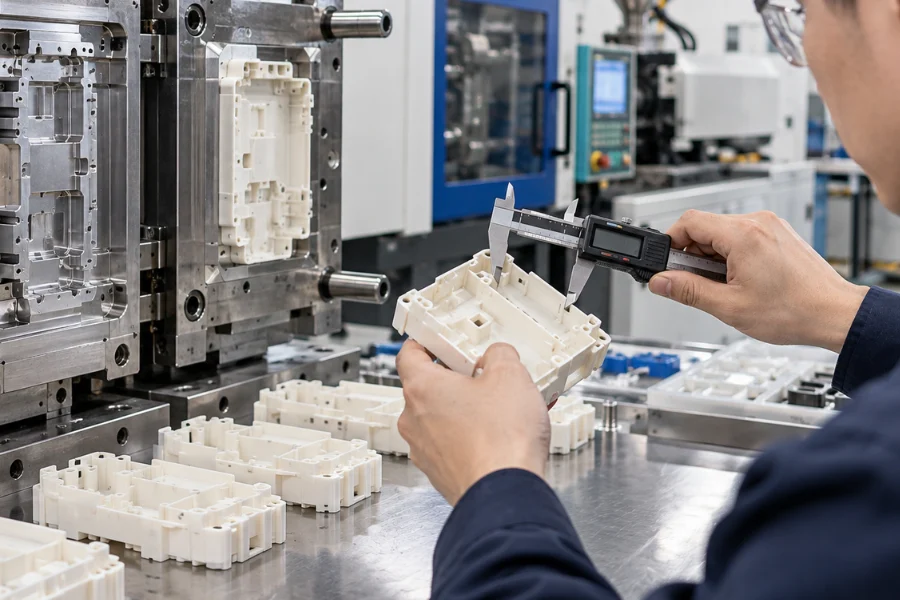
Injection molding is highly repeatable, but molded dimensions do not exactly match their nominal CAD values from shot to shot. Resin shrinkage, part geometry, cooling behavior, tooling, and process variation all influence the dimensions measured after molding.
For this reason, injection molding tolerances should be based on function rather than simply specifying the tightest value a mold can produce. A realistic tolerance must account for how the material shrinks, how the geometry affects cooling, and whether the process can maintain the required dimension consistently through production.
This guide explains typical tolerance references, the factors that control dimensional variation, and how to specify tighter tolerances where they are functionally justified.
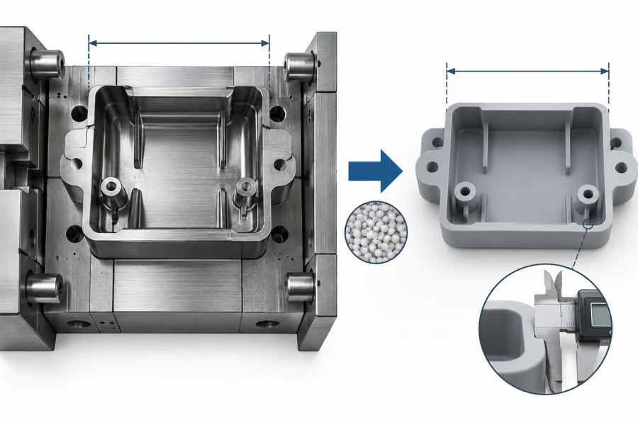
Injection molding tolerances define the allowable variation between a nominal design dimension and the actual dimension of the finished molded part. They are commonly expressed as a plus-or-minus value, such as 25.0 ±0.1 mm.
A critical distinction is that part tolerance is not the same as mold tolerance. A mold cavity may be CNC-machined to a tight tolerance, but the polymer changes dimension as it fills, packs, cools, shrinks, and reaches dimensional equilibrium after molding.
The relationship is better understood as:
Tool Accuracy → Material Shrinkage → Process Variation → Final Part Dimension
Accurate tooling is necessary for precision molding, but it does not by itself guarantee an equally tight molded-part tolerance.
For early design discussions, approximately ±0.1 mm is often used as a practical reference for general molded dimensions. Under suitable conditions, tolerances in the hundredths-of-a-millimeter range may be achievable for selected small, critical features.
These figures are general manufacturing references, not universal ISO tolerance grades or guaranteed molding capabilities. Actual tolerances depend on nominal dimension, resin grade, geometry, tooling, measurement conditions, and production stability.
The following values should therefore be treated as example references rather than universal specifications:
| Feature or Requirement | Example Reference | Important Qualification |
|---|---|---|
| General dimensional tolerance | About ±0.1 mm | Varies with material, dimension and geometry |
| Selected tight dimensions | Down to about ±0.025 mm under suitable conditions | Requires evaluation of tooling and process capability |
| Concentricity | Around ±0.125 mm | Depends on diameter, geometry and shrinkage |
| Roundness | Around ±0.175 mm | Sensitive to wall geometry and cooling |
| Flatness, up to 100 mm | Around ±0.400 mm | Strongly affected by warpage |
| Flatness, over 100 mm | Around ±0.800 mm | Larger surfaces increase warpage sensitivity |
Flash and ejector marks may be controlled separately. For example, a project specification may define an allowable flash or ejector-mark height rather than treating these conditions as part of a general dimensional tolerance.
The important engineering point is that there is no single tolerance value that applies equally to every injection molded material, feature, and part size.
Some molding suppliers and design guides group achievable tolerances into commercial and fine categories for practical comparison. Commercial tolerances provide more manufacturing freedom, while fine tolerances require greater dimensional control and generally cost more to maintain.
These terms should not automatically be interpreted as formal tolerance classes under a particular standard. Whenever a commercial or fine tolerance table is used, its definitions, material assumptions, and dimensional ranges should be checked.
The objective is not to minimize every tolerance. It is to identify the dimensions where tighter control is necessary for product function.
Tolerance standards provide a common framework for communicating dimensional requirements between part designers and molders.
ISO 20457:2026, Plastics moulded parts — Tolerances and acceptance conditions, addresses dimensional and geometrical tolerances, acceptance conditions, and technically achievable tolerances for molded plastic parts.
Its practical value is that molded-part tolerances can be considered in relation to functional requirements and manufacturing feasibility rather than simply applying machining-style tolerances to plastic components.
General tolerances can cover dimensions that do not require individual control, while functionally critical features can be specified directly when they require different or tighter limits.
GB/T 14486, Dimensional Tolerances for Moulded Plastic Parts, provides another reference for specifying dimensional tolerances for molded plastic components.
A tolerance standard creates a common specification framework, but it does not remove the need to evaluate the actual resin, geometry, mold, and production process. A tolerance that is technically defined on a drawing still has to be economically and repeatedly achievable in molding.
Dimensional accuracy is not controlled by one manufacturing variable. It develops from the interaction between material behavior, part design, tooling, and the molding process.
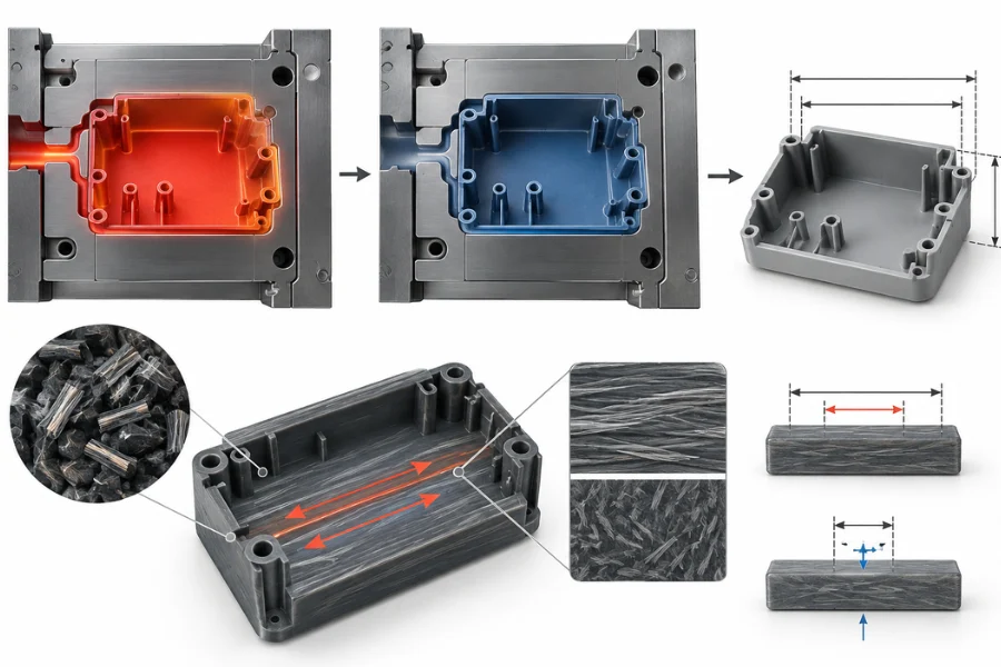
Molding shrinkage is one of the main contributors to final part dimensions. Mold cavities are normally sized to compensate for the expected contraction of the polymer as it cools.
However, shrinkage compensation is not the same as tolerance control.
Shrinkage compensation helps move the average molded dimension toward its nominal target. Tolerance control concerns the spread of dimensional variation around that target during production.
Correcting a cavity can therefore shift the dimensional mean closer to nominal, but it does not automatically reduce variation caused by changing mold temperatures, packing conditions, material behavior, or uneven cooling.
Different polymers also exhibit different shrinkage characteristics. Variation can occur between resin grades, formulations, fillers, and processing conditions.
Fiber-reinforced polymers add another consideration because fiber orientation during mold filling can create different shrinkage behavior parallel and perpendicular to flow. This anisotropy can affect both dimensions and warpage.
Supplier shrinkage data is therefore best treated as a design input rather than a guaranteed final-part value. Tool trials and actual molded measurements are needed to establish how a specific resin behaves in the real geometry and mold.
Tolerance capability generally becomes more difficult as the controlled dimension increases. Even a relatively small percentage of shrinkage produces a larger absolute dimensional change across a long dimension than across a short feature.
A tolerance that is practical across a 10 mm local feature may therefore be unrealistic across a 300 mm overall dimension.
Geometry also changes how the material fills, packs, cools, and develops internal stress. Large flat surfaces, long unsupported sections, abrupt section changes, and complex shapes can increase dimensional distortion.
The relevant question is therefore not only how tight the tolerance is, but also where that dimension is located and how the surrounding geometry behaves during molding.
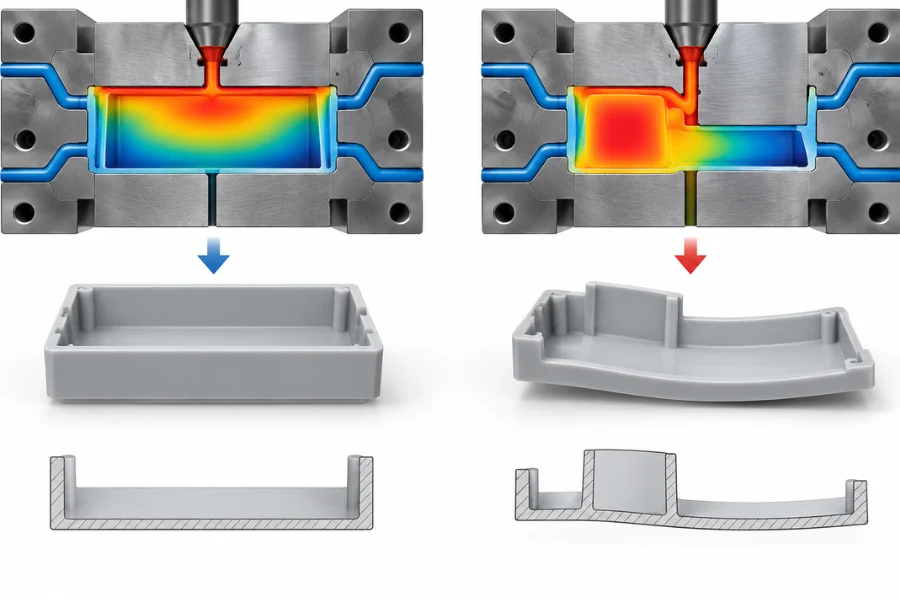
Wall thickness directly affects cooling and dimensional stability. Thick sections remain hot longer than thin sections, while abrupt thickness changes cause different regions to cool and contract at different rates.
The mechanism is:
Uneven Wall Thickness → Uneven Cooling → Differential Shrinkage → Warpage → Dimensional Variation
Uniform walls help make cooling and shrinkage more predictable. Where additional stiffness is required, ribs can often provide structural support without introducing unnecessarily thick sections.
Gradual wall transitions can also reduce localized shrinkage and internal stress. The DFM objective is not merely to follow a wall-thickness rule, but to create geometry that cools and shrinks as predictably as practical.
Tool accuracy matters, but mold design affects dimensional control through much more than cavity machining.
Cooling-channel placement influences how uniformly the molded part solidifies. An accurately machined cavity can still produce distorted parts if one region consistently cools faster than another.
Gate location affects filling and packing, which can change material orientation and local shrinkage. Dimensions crossing a parting line also deserve attention because mold alignment and parting-line mismatch introduce another source of variation.
Where practical, highly critical dimensions are easier to control when their defining features are contained within the same mold half.
Multi-cavity tooling introduces another requirement: dimensional consistency must be maintained both shot to shot and cavity to cavity.
Tight-tolerance molding requires both accuracy and repeatability.
Accuracy describes how closely the process is centered on the target dimension, while repeatability describes how consistently it reproduces that result. A process that repeatedly produces 25.30 mm is highly repeatable but still inaccurate if the requirement is 25.00 ±0.10 mm.
Injection pressure, holding pressure and time, material condition, mold temperature, and cooling can all shift dimensional results. Tight tolerances therefore require a stable process window centered on the target, not simply a precision mold or one successful sample.
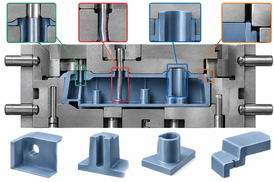
Different molded features respond differently to shrinkage, mold construction, and molding forces. Applying the same tolerance strategy to every feature can create unnecessary cost or unrealistic requirements.
| Part Feature | Main Tolerance Risk | Design or Tooling Consideration |
|---|---|---|
| Overall dimensions | Accumulated shrinkage | Consider resin behavior and overall size |
| Large flat surfaces | Warpage | Maintain uniform walls and balanced cooling |
| Through holes | Shrinkage and core geometry | Control core size, packing, and cooling |
| Deep blind holes | Core-pin deflection | Consider unsupported depth and melt pressure |
| Cylindrical features | Ovality | Balance wall geometry and cooling |
| Dimensions across parting lines | Mold mismatch | Avoid critical dimensions across the split where practical |
Deep blind holes demonstrate why feature geometry matters. A long core pin supported from one end can deflect under molding pressure, making the resulting hole diameter or position more difficult to maintain.
Likewise, a large thin-walled cylindrical feature can shrink unevenly and lose roundness even when its nominal diameter appears straightforward on the drawing.
Tolerance selection should therefore consider the molding mechanism behind the feature, not only its CAD dimension.
An individual molded component can meet its drawing requirements and still create problems after assembly.
For example, several molded parts connected by a common fastener may each have acceptable hole dimensions and locations, but accumulated variation can still prevent the holes from aligning correctly.
The same principle applies to snap-fit housings, mating shells, connectors, bearing locations, and plastic-to-metal assemblies. Tolerance analysis should therefore focus on the complete functional chain rather than evaluating every component in isolation.
Tolerance control is most effective when addressed before tooling is manufactured.
Start with dimensions that directly control fit, sealing, alignment, motion, or assembly. These may also be treated as critical-to-quality (CTQ) dimensions when dimensional performance directly affects the product requirement.
A drawing filled with tight tolerances does not necessarily describe a more precise product. It may simply make the part more difficult to manufacture.
Use appropriate general tolerances for non-critical features and specify tighter limits only where product function justifies them.
This allows tooling, process-development, and inspection resources to be concentrated on the dimensions that matter.
Maintain reasonably uniform walls, use gradual transitions, and avoid unnecessary material concentrations. Evaluate ribs, bosses, gates, cores, and other features according to how they affect flow, packing, cooling, and shrinkage.
Shrinkage cannot be eliminated. The objective is to make it predictable enough to compensate and repeatable enough to control.
Tolerance should be considered during material selection rather than after the resin has been finalized.
For dimensionally sensitive features, evaluate shrinkage behavior, moisture response, thermal expansion, fillers, and dimensional stability alongside mechanical and chemical requirements. The tooling and molding process can then be developed around those material characteristics.
Initial tool trials provide an opportunity to compare predicted shrinkage with actual molded dimensions and make appropriate tool corrections. However, a dimension achieved on a T1 sample is not automatically a production-capable tolerance.
Validation should determine whether critical dimensions remain within specification across repeated cycles and, where applicable, across multiple cavities. For critical production dimensions, capability metrics such as Cp and Cpk may be used to evaluate whether an established process can consistently operate within specification.
Dimensional inspection also needs to be appropriate for the tolerance being evaluated. Measurement equipment and methods should provide sufficient resolution and repeatability relative to the specified tolerance.
Inspection conditions should also be defined where dimensional stability is sensitive to temperature, humidity, post-molding conditioning, or measurement timing. A dimension measured immediately after molding may not represent the same condition as a part measured after stabilization.
The goal is to demonstrate that the manufacturing and measurement systems can maintain and verify the requirement—not simply that a few samples happened to fall inside the tolerance band.
The cost of tighter tolerances comes primarily from the manufacturing controls required to maintain them consistently.
Depending on the application, tighter requirements may involve:
In some applications, dimensional requirements may also limit how aggressively cooling time and overall cycle time can be reduced.
The relationship is:
Tolerance Requirement → Manufacturing Control → Production Risk → Cost
The most economical specification is therefore usually the widest tolerance that still protects product function, rather than the smallest tolerance technically achievable.
A practical tolerance strategy starts with the functional requirement:
Function → Critical Dimension → Material Behavior → Part Geometry → Tooling → Process Capability → Inspection → Final Tolerance
Use general tolerances for non-critical dimensions and tighter individual requirements for interfaces where dimensional variation affects fit, sealing, alignment, motion, or performance.
For assemblies, evaluate tolerance stack-up before tooling so that manufacturing effort is concentrated on the dimensions that actually control final product function.
Approximately ±0.1 mm is often used as a general manufacturing reference, but it is not a universal standard. Actual capability depends on the material, nominal dimension, geometry, tooling, and process stability.
Tolerances in the hundredths-of-a-millimeter range may be possible for selected critical features under controlled conditions. The requirement should be evaluated against resin behavior, feature geometry, tooling, process capability, and inspection capability rather than assumed for an entire part.
The mold can be machined accurately, but the polymer subsequently fills, packs, cools, and shrinks. These material and process effects introduce dimensional variation beyond the machining tolerance of the cavity itself.
Materials with relatively predictable dimensional behavior can simplify tolerance control, but no resin is universally best. Shrinkage, reinforcement, moisture response, thermal expansion, geometry, and processing conditions all need to be considered.
Often they do. Larger dimensions experience greater absolute dimensional change from shrinkage and may be more sensitive to warpage and cooling differences, making a tight tolerance across a large dimension harder to maintain than the same tolerance on a small local feature.
Injection molding tolerance should be driven by function, not by the smallest number that appears achievable.
A robust specification balances material behavior, geometry, tooling capability, process stability, measurement capability, cost, and the dimensions that actually control product performance.