Physical Address
304 North Cardinal St.
Dorchester Center, MA 02124
Physical Address
304 North Cardinal St.
Dorchester Center, MA 02124
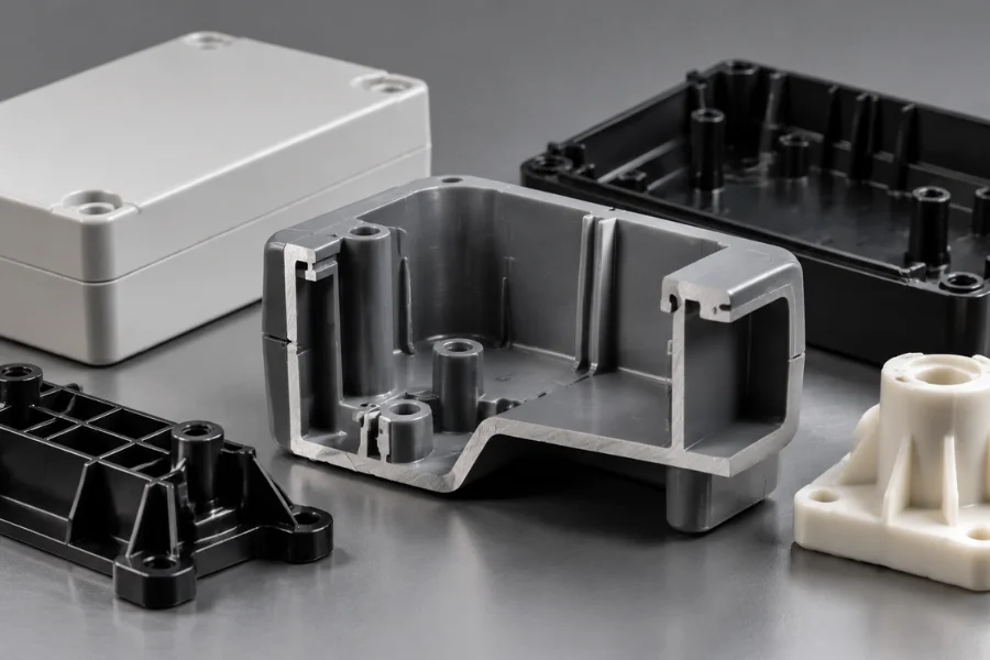
Wall thickness affects mold filling, cooling time, shrinkage, and the mechanical performance of injection molded parts. Thin sections can restrict melt flow and cause short shots, while thick sections may cool unevenly and develop sink marks or internal voids.
A nominal wall thickness of approximately 2–4 mm is a common starting point for many conventional thermoplastic parts. The appropriate value depends on resin grade, flow length, part geometry, structural loads, and molding conditions.
This guide explains how to select wall thickness, optimize local geometry, prevent thickness-related defects, and validate designs before mold manufacturing.
Wall thickness is the distance between opposing surfaces of a molded plastic section. The nominal wall thickness is the primary thickness maintained across the main body of a part. Ribs, bosses, and mounting features may have different local dimensions to meet structural requirements.
Consistent nominal thickness generally promotes more uniform filling, cooling, and shrinkage. However, the design must also accommodate load-bearing features, fastening requirements, and the limitations of the selected molding process.
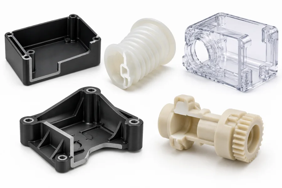
Thermoplastics differ in melt viscosity, shrinkage, stiffness, and processing requirements. These differences affect both the minimum practical wall thickness and the risk of dimensional defects.
The following ranges are general starting references for conventional injection molding, not material specifications or guaranteed processing limits.
| Plastic Material | General Starting Range | Key Design Consideration |
|---|---|---|
| ABS | 1.1–3.6 mm | Surface appearance, stiffness, and sink marks |
| Polypropylene (PP) | 0.6–3.8 mm | Crystalline shrinkage, flexibility, and warpage |
| Polycarbonate (PC) | 1.0–3.8 mm | Melt flow resistance and filling pressure |
| Nylon (PA) | 0.8–2.9 mm | Resin grade, moisture behavior, and reinforcement |
| Acetal (POM) | 0.8–3.0 mm | Crystalline shrinkage and dimensional control |
| Polyethylene (PE) | 0.8–5.1 mm | Material grade, shrinkage, and thick-section cooling |
| Polystyrene (PS) | 0.9–3.8 mm | Brittleness, impact requirements, and stress concentration |
These rounded ranges are preliminary design references adapted from general injection molding guidance. They do not apply uniformly to every resin grade. Confirm the selected thickness against the material supplier’s recommendations and the actual part geometry.
Melt viscosity and flow length jointly influence filling difficulty. A 1 mm wall in a small component with a short flow path may fill reliably, while the same thickness in a large enclosure may require substantially more injection pressure.
Shrinkage behavior also matters. Semicrystalline polymers such as PP, PA, and POM can exhibit significant molding shrinkage, depending on grade and processing conditions. Glass-fiber reinforcement can improve stiffness but introduce directional shrinkage differences because fibers align with the melt flow.
Material selection should therefore account for the longest flow path, the thinnest section, the required mechanical properties, and the dimensional stability of the finished part.
Wall thickness must satisfy both structural requirements and molding constraints. A section can be strong enough in service yet too thin to fill reliably. Increasing thickness may solve a structural problem but create additional cooling and shrinkage risks.
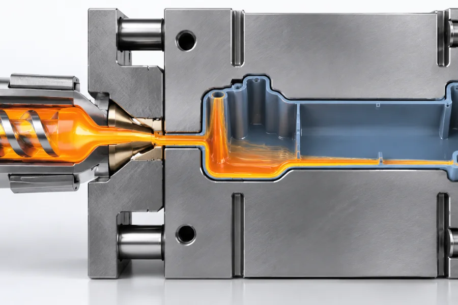
Thin walls restrict melt flow while heat transfers from the plastic into the mold. As the material near the cavity surfaces cools, the effective flow channel narrows. If the melt cannot reach the end of the cavity before flow becomes restricted, a short shot may occur.
The minimum practical thickness depends on five interacting factors:
Some thermoplastics can be molded below 1 mm, but this is not a universal capability. Thin-wall feasibility depends on the complete flow path, material, equipment, and tooling.
A practical evaluation starts with a material-appropriate thickness, identifies the longest flow path and thinnest sections, and checks whether the cavity can fill within the available processing window. If feasibility remains uncertain, mold flow analysis or representative molding trials can help determine whether the design, gate location, or material needs to change.
Thick sections retain heat longer because heat must travel farther from the plastic’s interior to the mold surfaces. In simplified heat-transfer models, cooling time increases approximately with the square of wall thickness when material properties and temperature conditions remain comparable. Actual cycle time also depends on geometry, cooling efficiency, and the temperature required for safe ejection.
Thick regions create a second risk when the surrounding material or gate solidifies before the interior has completed its shrinkage. Once the packing path closes, additional holding pressure cannot effectively compensate for shrinkage in an isolated region.
Instead of applying a universal maximum thickness, engineers should identify unnecessary solid sections and evaluate whether coring or structural reinforcement can preserve strength with less material accumulation.
Wall thickness must withstand operating loads, assembly forces, and handling without excessive deformation. A thin enclosure wall, for example, may resist ordinary handling but deform around a fastener under concentrated loading.
Evaluate expected loads, allowable deflection, fastening forces, long-term creep, and the stiffness needed for mold ejection. Where geometry permits, ribs or gussets can increase stiffness without thickening the entire part. The final design must balance mechanical performance against filling, cooling, and dimensional stability.
Large thickness differences cause adjacent regions to cool and shrink at different rates. The resulting differential contraction can produce residual stress, surface distortion, or warpage.
During CAD review, identify material concentrations at wall intersections, mounting blocks, and other junctions. Consistent nominal thickness reduces these risks, especially in large flat surfaces and precision housings.
Where different thicknesses are functionally necessary, keep the difference as small as practical and introduce it gradually. Abrupt cross-section changes can alter flow resistance and create localized differences in cooling and shrinkage.
Tapered transitions and appropriately designed radii help smooth these changes. The transition should be evaluated against the material, flow direction, and structural loading rather than a universal thickness ratio.
Coring removes unnecessary plastic while preserving the part’s external geometry and structural support.
For example, a solid mounting block attached to a thin housing wall can create a concentrated mass of plastic that cools more slowly than the surrounding section. Replacing the solid block with a cored structure and appropriately positioned ribs can reduce material accumulation, cooling demands, and the risk of sink marks or internal voids.
The remaining walls and supports must still withstand assembly loads and ejection forces.
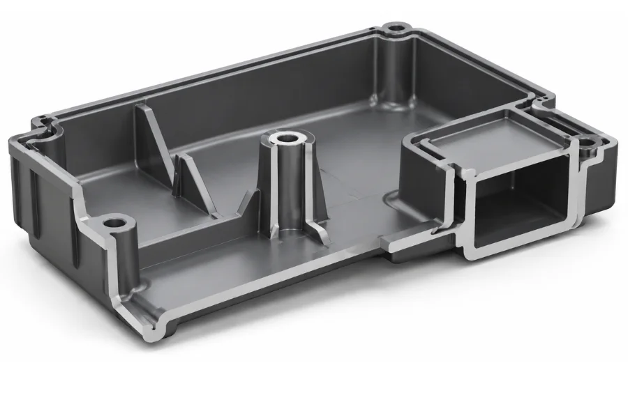
Ribs increase stiffness without requiring a thicker nominal wall. However, the rib-wall junction creates a locally thicker section that can produce sink marks on the opposite surface.
For appearance-sensitive thermoplastic parts, a rib base thickness of approximately 40–60% of the adjoining nominal wall is a common preliminary guideline. The appropriate ratio depends on the resin, rib geometry, structural requirements, and surface finish. Ribs also need suitable draft for mold release and a base radius to reduce stress concentration.
A solid screw boss can create similar material accumulation. A cored boss supported by properly designed ribs can reduce the thick section while maintaining fastening strength. Its dimensions must still accommodate the fastener and expected loads.
Rounded corners reduce stress concentration and help avoid abrupt geometric changes. An inside radius of approximately half the nominal wall thickness is a common starting point. For a constant-thickness curved section with concentric surfaces, the outside radius equals the inside radius plus the nominal wall thickness. Verify the resulting geometry against structural requirements and available molding space.
Wall thickness can affect filling, packing, cooling, and ejection, but it is rarely the only cause of a molding defect.
| Defect | Wall Thickness-Related Mechanism | Corrective Direction |
|---|---|---|
| Short shots | Thin sections restrict flow or freeze before filling is complete | Review thickness, flow length, gate design, and filling conditions |
| Sink marks | Localized shrinkage creates surface depressions near thick sections | Reduce material accumulation and evaluate packing |
| Internal voids | Thick-section shrinkage creates internal cavities when compensation is insufficient | Core thick regions and review packing effectiveness |
| Warpage | Differential cooling and shrinkage distort the part | Improve thickness distribution and cooling balance |
| Residual stress | Uneven shrinkage and constrained deformation create internal stress | Improve transitions and review processing conditions |
| Ejection deformation | Thin or unsupported walls deform under removal forces | Improve local support and distribute ejection forces |
Sink marks appear as surface depressions, while internal voids are cavities within the molded section. Both can result from insufficient compensation for shrinkage in thick regions.
The outcome depends on material behavior, local geometry, surface solidification, and packing conditions. Increasing packing pressure may help while the gate remains open, but it cannot effectively compensate for an isolated region after the packing path has frozen. Reducing unnecessary material accumulation is often a more robust design solution than relying solely on process adjustments.
Gate position determines how melt enters the cavity and how packing pressure reaches different regions. Placing a gate near a thick section can help maintain an effective packing path while that region solidifies, but gating into the thickest area is not always optimal.
Gate selection must also consider flow balance, weld lines, appearance requirements, pressure loss, and overpacking. If a thin section between the gate and a thick region freezes early, packing pressure may no longer reach the material that needs compensation. Gate placement should therefore be evaluated alongside wall thickness distribution and expected solidification behavior.
Cooling channels influence heat removal and temperature distribution across the molded part. Thick regions generally retain heat longer, so their location should be considered when planning the cooling layout.
Cooling channels can be positioned to improve heat removal where mold construction permits, but they must not compromise mold strength or interfere with ejector pins, inserts, and other tooling features. The objective is balanced cooling that supports dimensional stability and reliable ejection, not simply maximum cooling near every thick section.
Thin walls may deform if ejection forces are concentrated on areas that lack sufficient support. Where geometry permits, position ejector pins beneath supported regions such as ribs or bosses. If direct support is limited, a larger contact area or alternative ejection arrangement can distribute the load.
The part must also be sufficiently cool to retain its shape during removal. Cooling and ejection design should therefore be evaluated together.
Wall thickness affects resin consumption, cycle time, production output, and defect risk.
Thicker walls use more material and may extend cooling time when cooling is the cycle-limiting stage. Thin walls reduce material volume but can require higher filling pressure, more demanding tooling, or a narrower processing window.
A design that saves resin but produces frequent short shots or dimensional variation may cost more than a slightly thicker, more stable alternative. The appropriate target is the thickness that meets functional requirements without unnecessary material accumulation or excessive manufacturing complexity.
Use the following sequence to review wall thickness before mold manufacturing.
Simulation results depend on material data and modeling assumptions. Confirm critical designs through molding trials, dimensional inspection, and functional testing where required.
There is no universal ideal thickness. Approximately 2–4 mm is a common starting range for many conventional thermoplastic parts, but the appropriate value depends on resin grade, flow length, geometry, and functional loads. Use material-specific guidance and confirm feasibility through DFM evaluation and molding validation.
Yes. Some thermoplastics can be molded below 1 mm when the material, flow path, equipment, tooling, and processing conditions are suitable. Thin walls increase filling resistance, so feasibility must be evaluated for the complete part rather than the minimum wall dimension alone.
No. Greater thickness can improve stiffness and load capacity in some geometries, but performance also depends on material properties, stress concentration, reinforcement, and loading conditions. Excessive thickness may increase shrinkage defects and cooling time. Ribs or gussets can sometimes provide a more efficient structural solution.
Yes. Thick and thin regions may cool and shrink at different rates, contributing to warpage and dimensional variation. Actual tolerances also depend on resin properties, mold construction, process stability, part geometry, and the location of the specified features.
Review nominal thickness, thin flow restrictions, thick material concentrations, and transitions in the CAD model. DFM analysis can identify potential manufacturing concerns, while mold flow simulation can help evaluate filling, packing, and cooling. Trial molding and part inspection are needed to confirm actual manufacturing performance and dimensional stability.
Injection molding wall thickness must balance material properties, structural requirements, and manufacturing feasibility. Consistent walls, gradual transitions, and efficient reinforcement help control filling, cooling, and shrinkage while avoiding unnecessary material and production costs.