Physical Address
304 North Cardinal St.
Dorchester Center, MA 02124
Physical Address
304 North Cardinal St.
Dorchester Center, MA 02124
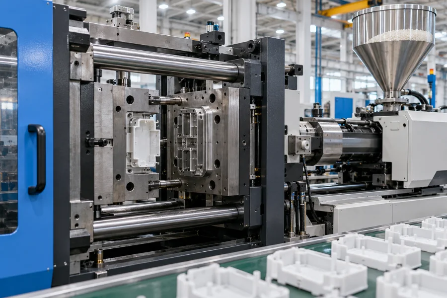
Injection molding turns polymer material into repeatable parts through a controlled cycle of plasticizing, filling, packing, cooling, and ejection. The basic concept is simple; the engineering challenge is reproducing the required geometry and quality consistently over repeated production cycles.
That consistency depends on more than the molding machine. Material behavior, part geometry, mold design, processing conditions, cooling, and production volume all influence whether a component can be manufactured reliably and economically.
This guide explains how injection molding works, what controls molded-part quality, and what engineers and buyers should evaluate before committing to production tooling.
Injection molding is a manufacturing process in which polymer material is heated until it can flow, injected under pressure into a closed mold cavity, cooled until sufficiently rigid, and then ejected.
Thermoplastics are commonly processed this way because they soften when heated and solidify during cooling. The mold defines the part geometry, while the machine provides the controlled heat, pressure, motion, and clamping required for each molding cycle.
The basic manufacturing relationship is:
Material → Plasticizing → Mold Filling → Packing → Cooling → Ejection → Molded Part
Producing a good part requires control of the interactions behind this sequence. Material flow affects filling, geometry affects cooling and shrinkage, mold design influences temperature distribution and ejection, and process settings affect dimensional consistency.
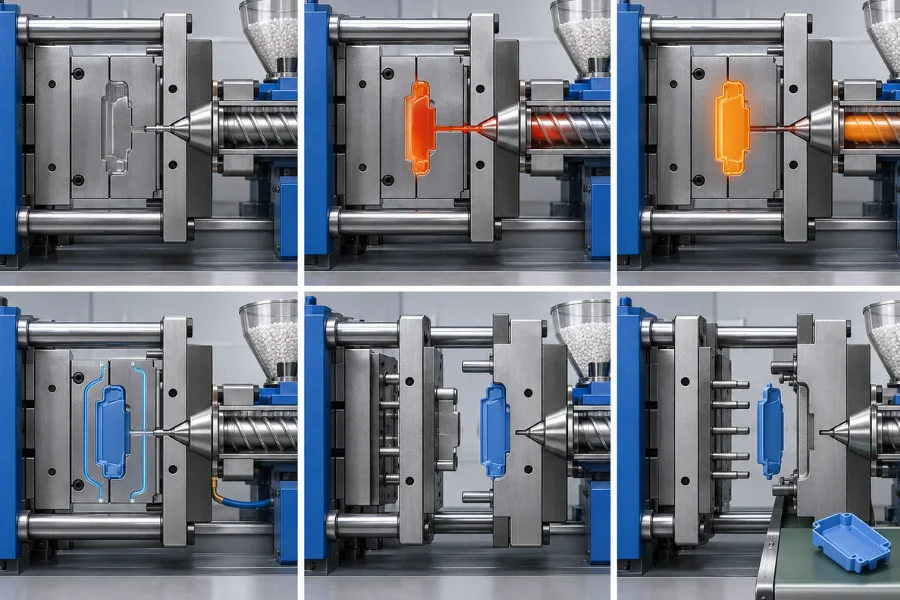
A typical injection molding cycle can be divided into six main stages. Each stage has a specific function, and problems at one stage can influence the final part.
Before injection, the two mold halves close and are held together by the machine’s clamping unit.
The clamp must resist the forces generated by pressure inside the cavities. Insufficient clamping capacity can allow slight mold separation and contribute to flash around the parting line.
Polymer pellets enter a heated barrel where a rotating screw conveys, compresses, heats, and mixes the material into a flowable melt.
The screw then moves forward and forces the polymer through the nozzle and mold feed system into the cavity. Melt condition, injection speed and pressure, material flow behavior, gate design, and part geometry all affect whether the cavity fills correctly.
Filling the cavity does not complete the molding process because the polymer begins to contract as it cools.
Holding pressure continues supplying material to compensate for part of this volumetric shrinkage while pressure can still be transmitted through the gate. Poor packing control can contribute to sink marks, voids, dimensional variation, or excessive molded-in stress.
The polymer transfers heat into the mold until the part becomes sufficiently rigid for removal.
Cooling conditions influence both cycle time and dimensional behavior. Uneven wall sections or nonuniform cooling can create different shrinkage rates across the part, increasing the risk of warpage and dimensional variation.
After sufficient cooling, the clamping unit separates the mold halves.
The component should remain on the intended mold side for predictable ejection. Shrinkage, draft, surface texture, and mold geometry all influence how easily the part releases.
Ejector pins, sleeves, stripper systems, or other mechanisms remove the molded component.
The part must be rigid enough to withstand ejection without excessive deformation or surface damage. Once it is removed, the mold closes and the next cycle begins.
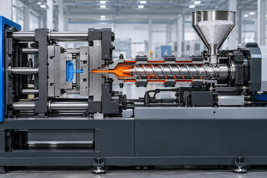
An injection molding machine provides the thermal and mechanical conditions needed to repeat this cycle.
The injection unit plasticizes, meters, and delivers the polymer. Modern thermoplastic molding commonly uses a reciprocating screw that rotates to prepare the melt and then moves forward to inject it.
The clamping unit closes and holds the mold during filling and packing, then opens it for part removal.
Machine capability must match the molding application. Required shot size, injection pressure, clamping demand, mold dimensions, and material characteristics all influence whether a particular machine is suitable for a mold and part.
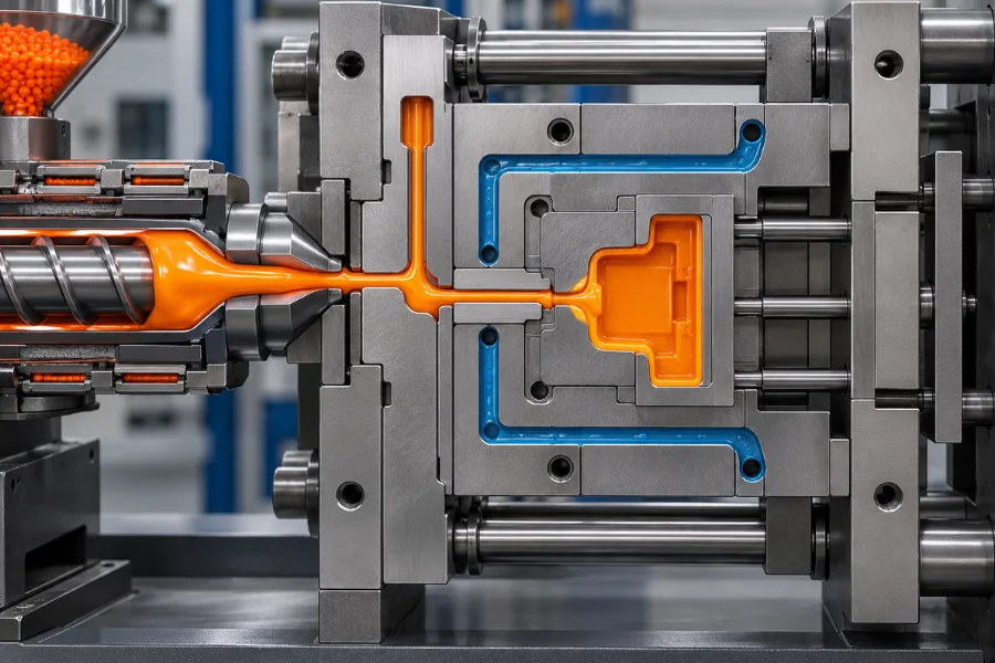
The machine supplies the processing conditions, but the mold controls how the polymer enters the cavity, takes shape, loses heat, and is released.
A mold may contain cavities and cores, runners, gates, vents, cooling channels, and an ejection system. More complex components may require additional mechanisms such as slides or lifters.
The relationship is:
Part Geometry → Mold Architecture → Material Flow → Cooling and Shrinkage → Ejection → Part Quality
Gate location, for example, affects the filling pattern and where separate flow fronts meet. Cooling-channel design influences temperature uniformity, while draft and ejection design affect reliable part release.
In multi-cavity molds, runner and cavity balance also matter because each cavity should fill, pack, cool, and produce parts as consistently as practical.
A mold therefore does more than reproduce CAD geometry. It must support repeatable filling, pressure transfer, cooling, venting, and ejection throughout production.
Injection molding can process many polymers, but thermoplastics are among the most common. Examples range from commodity materials such as PP and PE to engineering plastics such as ABS, PC, PA, POM, and PBT. Higher-performance applications may use materials such as PEEK, PEI, or PPS, while flexible components can use suitable TPE or TPU grades.
The more important manufacturing question is not simply whether a polymer can be injection molded, but how it behaves during the process.
Material properties can influence molding in several ways:
A material that meets the finished product’s mechanical requirements may therefore introduce additional molding or tooling considerations.
Actual processing conditions should be established using resin supplier recommendations and validated for the specific material grade, part geometry, mold, and machine.
Molded-part quality develops from the interaction between the material, component geometry, mold, machine, and process settings.
Melt temperature affects viscosity and flow. Insufficient melt preparation can make filling more difficult, while excessive thermal exposure may increase degradation risk for temperature-sensitive polymers.
Injection speed and pressure influence how the melt advances through the cavity. They must provide adequate filling without creating unnecessary flow, venting, or stress-related problems.
Packing pressure and time influence shrinkage compensation after filling. Their effect depends on wall thickness, gate behavior, polymer characteristics, and cooling.
Mold temperature and cooling affect surface replication, shrinkage, dimensional stability, warpage, and cycle time.
These relationships explain why stable molding requires a process window rather than one supposedly ideal set of machine settings. The appropriate conditions depend on the specific resin grade, geometry, mold, and production equipment.
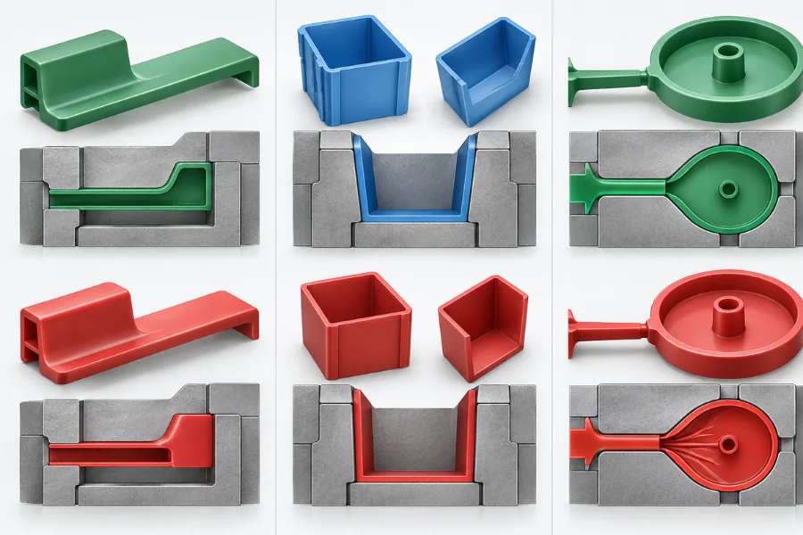
Many injection molding problems begin with part geometry before production tooling is manufactured.
Design for manufacturability evaluates whether the geometry is compatible with material flow, cooling, mold construction, and ejection.
Three relationships illustrate why:
Ribs, bosses, undercuts, parting lines, and cosmetic surfaces can also influence tooling complexity and process stability.
DFM is therefore most valuable before tooling is finalized, when geometry can still be changed without expensive mold rework.
Injection molding defects rarely have one universal cause. Effective troubleshooting requires identifying the mechanism behind the visible symptom.
| Defect | Factors to Investigate | Typical Mechanism |
|---|---|---|
| Short shot | Material flow, temperature, pressure, gate, venting, geometry | Melt cannot completely fill the cavity |
| Flash | Cavity pressure, clamping, mold fit, parting-line condition | Melt escapes through an unintended mold gap |
| Sink marks | Thick sections, packing, gate behavior, cooling | Localized shrinkage produces a surface depression |
| Warpage | Geometry, material behavior, orientation, cooling | Nonuniform shrinkage distorts the part |
| Weld lines | Gate location, flow pattern, temperature, venting | Separate melt fronts meet during filling |
A machine adjustment may reduce a symptom without correcting its root cause. Increasing injection pressure, for example, may not permanently solve incomplete filling if an overly restrictive flow path or inadequate venting is responsible.
Troubleshooting should therefore consider material, part design, mold, process, and equipment together.
Injection molding is particularly effective when the same geometry must be produced repeatedly.
Once the part design, mold, material, and process are stable, automated cycles and multi-cavity tooling can support high production rates while distributing tooling and development costs across more parts.
The main limitation is the upfront commitment. Mold design and manufacturing require time and capital, and significant geometry changes after tooling can require costly modifications.
The fundamental manufacturing trade-off is:
Tooling Investment + Process Development → Repeatable Production → Lower Unit Cost at Sufficient Volume
Injection molding is therefore not automatically the lowest-cost manufacturing process. Its economics depend on tooling complexity, cycle time, cavitation, expected production quantity, material, quality requirements, and the stability of the product design.
Injection molding becomes a strong manufacturing option when the product, tooling strategy, and expected production volume support one another.
A practical decision sequence is:
Part Requirements → Material → Geometry → Tooling → Production Volume → Process Validation
Before committing to production tooling, engineers and buyers should consider:
Injection molding is generally more attractive for repeatable production with relatively stable geometry. For early prototypes, rapidly changing designs, or very low quantities, machining, additive manufacturing, or prototype tooling may offer greater flexibility.
Across automotive, medical, electronics, industrial, consumer, and packaging applications, the underlying reason for choosing injection molding is similar: suitable material and geometry can be converted into repeatable parts efficiently once the tooling and process have been established.
Injection molding should be understood as more than forcing molten plastic into a cavity.
Reliable production depends on an interconnected system:
Material → Part Design → Mold → Process Window → Cooling and Shrinkage → Part Quality → Production Economics
When these elements are considered together, injection molding can provide repeatable and scalable plastic-part production. When they are treated independently, problems that appear to be machine or process issues may actually originate in the material, geometry, or tooling.
Initial costs can include mold design, tooling, manufacturing engineering, trials, and process development. Once production is stable, those upfront costs can be distributed across more parts while automated molding cycles reduce the manufacturing effort required per component.
Major factors include part geometry, mold complexity, number of cavities, material, cycle time, production quantity, quality requirements, and any secondary operations. Tooling cost and part cost should therefore be evaluated together rather than separately.
There is no universal cycle time. It depends on factors such as material, wall thickness, part size and geometry, mold temperature, cooling design, and ejection requirements.
It can be, depending on part value, tooling strategy, geometry, and quality requirements. For very low quantities or frequently changing designs, prototype tooling, machining, or additive manufacturing may sometimes be more economical.
Defects can originate from material condition, part geometry, mold design, machine capability, processing conditions, or interactions among them. Troubleshooting should identify the underlying mechanism before parameters are changed.