Physical Address
304 North Cardinal St.
Dorchester Center, MA 02124
Physical Address
304 North Cardinal St.
Dorchester Center, MA 02124
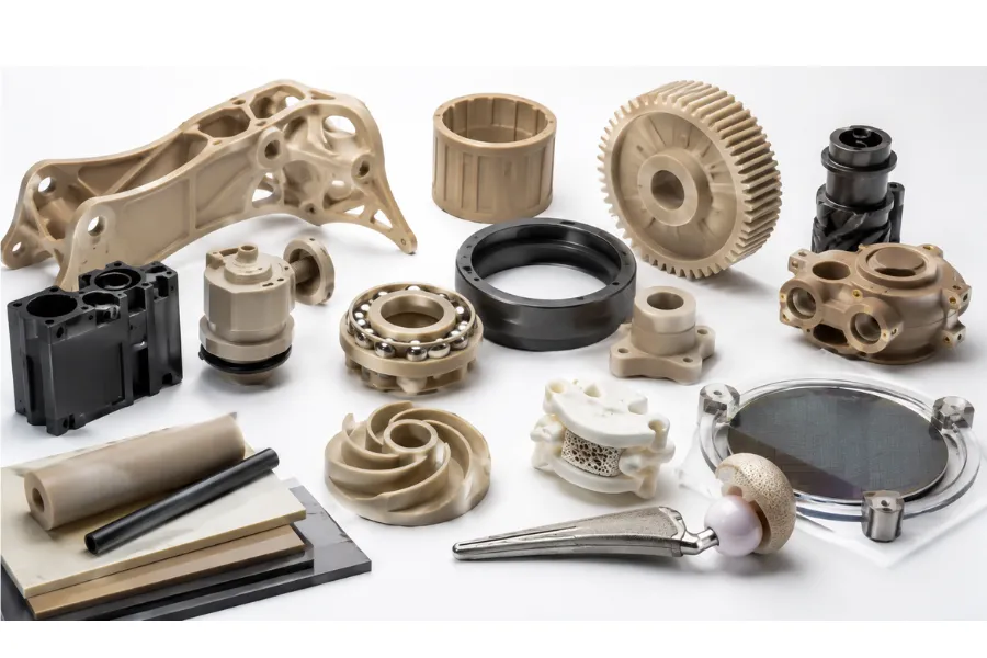
Selecting the right engineering material is no longer simply a matter of comparing mechanical properties. As products become lighter, more compact, and expected to operate in increasingly demanding environments, materials must withstand combinations of high temperatures, aggressive chemicals, cyclic loading, sterilization, and tight dimensional tolerances throughout their service life. In many cases, conventional engineering plastics such as nylon, polycarbonate, or acetal reach their practical performance limits long before the product reaches the end of its intended lifecycle.
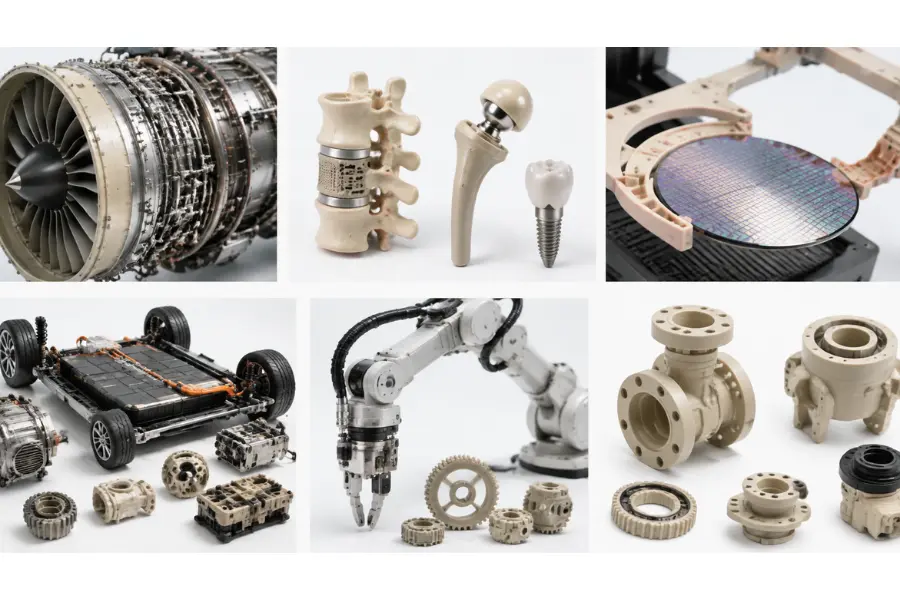
This is why PEEK material (Polyether Ether Ketone) has become one of the most widely specified high-performance thermoplastics in aerospace, medical devices, semiconductor manufacturing, automotive systems, and industrial equipment. Rather than excelling in only one characteristic, PEEK offers an exceptional balance of thermal stability, mechanical strength, wear resistance, chemical resistance, and long-term dimensional accuracy.
However, selecting PEEK is rarely a straightforward decision. Its premium material cost, demanding processing conditions, and specialized manufacturing requirements mean engineers must evaluate not only material performance but also production volume, manufacturing capability, lifecycle cost, and application risk. This guide explains what PEEK material is, how its molecular structure determines its engineering performance, where it delivers the greatest value, and what designers should consider before specifying it for production.
PEEK (Polyether Ether Ketone) is a semi-crystalline high-performance thermoplastic belonging to the polyaryletherketone (PAEK) family. Developed for applications where conventional engineering plastics cannot maintain long-term reliability, PEEK has become one of the few polymers capable of replacing metals in demanding environments without sacrificing structural performance.
Unlike commodity plastics designed primarily for low-cost manufacturing, PEEK is engineered for applications requiring a combination of:
With a density of approximately 1.30 g/cm³, PEEK weighs roughly half as much as aluminum while maintaining excellent stiffness and strength. For many lightweight engineering systems, this enables designers to reduce component mass without compromising reliability.
More importantly, PEEK is rarely selected because it possesses the highest value in a single property. Engineers choose it because very few materials can maintain consistent performance when multiple demanding conditions occur simultaneously.
The exceptional performance of PEEK originates from its carefully balanced molecular architecture rather than from additives or reinforcement alone.
Its polymer backbone consists of three primary structural elements:
Each contributes differently to the material’s behavior.
The aromatic rings provide a rigid backbone that resists thermal deformation and contributes to high mechanical stiffness. Ketone groups strengthen intermolecular interactions, improving creep resistance, dimensional stability, and load-bearing capability under continuous stress. Ether linkages introduce sufficient molecular flexibility to allow melt processing while preserving excellent toughness.
This combination enables PEEK to achieve properties that are often difficult to balance in other engineering plastics:
Rather than optimizing a single performance metric, PEEK’s molecular design creates a balanced engineering material capable of operating reliably across multiple demanding environments.
One characteristic frequently overlooked in general material introductions is that PEEK is semi-crystalline, and this directly influences both manufacturing and product performance.
Compared with amorphous engineering plastics, semi-crystalline polymers generally provide:
However, these advantages introduce additional manufacturing complexity.
As molten PEEK cools inside the mold, crystalline regions continue developing. The degree of crystallization directly affects the finished component’s:
Consequently, two parts molded from the same resin can exhibit different mechanical performance if processed under different mold temperatures or cooling conditions.
For manufacturing engineers, controlling crystallization is just as important as selecting the correct raw material.
Engineering plastics are generally categorized according to the environments they are designed to withstand.
| Material Category | Typical Materials | Typical Applications |
|---|---|---|
| Commodity Plastics | PE, PP, PVC | Consumer products, packaging |
| Engineering Plastics | ABS, PC, PA, POM | Mechanical parts, electrical housings |
| High-Performance Polymers | PEEK, PEKK, PEI, PPS | Aerospace, medical, semiconductor, energy |
PEEK occupies the highest category because it combines several critical engineering properties that are rarely found together in one polymer.
Instead of optimizing only one characteristic, PEEK simultaneously provides:
This balanced property profile explains why PEEK is frequently specified for mission-critical components where failure could result in expensive downtime, safety concerns, or difficult maintenance.
Material selection should never rely on a single datasheet value.
Experienced engineers evaluate how a material behaves throughout its entire service life, considering temperature, mechanical loading, manufacturing variability, environmental exposure, and expected maintenance requirements.
The following properties are among the most important when evaluating PEEK.
| Property | Typical Value | Engineering Significance |
|---|---|---|
| Density | 1.30 g/cm³ | Lightweight alternative to aluminum and steel |
| Tensile Strength | 90–100 MPa | Suitable for structural load-bearing components |
| Glass Transition Temperature (Tg) | 143°C | Maintains stiffness under elevated temperatures |
| Melting Temperature (Tm) | 343°C | Supports high-temperature processing |
| Continuous Service Temperature | Up to 250°C | Reliable long-term operation in demanding environments |
| Water Absorption | Approximately 0.4% | Excellent dimensional stability in humid conditions |
| Flammability | UL94 V-0 | Flame resistant without additives |
| Chemical Resistance | Resistant to most industrial chemicals | Suitable for aggressive process environments |
Many materials advertise impressive melting temperatures, but engineers are generally more concerned with continuous operating performance.
PEEK’s melting point of approximately 343°C is only one part of the picture.
More important is its ability to retain stiffness, fatigue resistance, and dimensional accuracy during prolonged exposure to temperatures approaching 250°C.
This allows engineers to specify PEEK for applications including:
Unlike many engineering plastics that rapidly lose stiffness as temperature increases, PEEK maintains stable mechanical performance throughout extended service periods.
PEEK provides tensile strengths approaching 100 MPa while weighing approximately half as much as aluminum.
This combination enables engineers to improve:
Reducing moving mass also lowers inertia, improving positioning accuracy and reducing actuator loads in precision automation systems.
For aerospace and robotics applications, these secondary performance benefits are often just as valuable as the material’s mechanical strength.
Static strength alone rarely determines component life.
Many engineering failures occur after millions of repeated operating cycles under relatively modest loads.
PEEK performs exceptionally well in applications involving:
Typical components include:
For these applications, engineers often specify reinforced or bearing-grade PEEK to further improve wear resistance while reducing maintenance intervals.
PEEK maintains excellent resistance to most industrial chemicals, including oils, fuels, hydraulic fluids, cleaning agents, and high-pressure steam.
Unlike many engineering plastics that gradually absorb moisture and lose dimensional accuracy, PEEK exhibits extremely low water absorption, helping maintain tight tolerances throughout long service periods.
This property is particularly valuable for:
One important limitation should still be considered.
PEEK is not resistant to concentrated sulfuric acid, and engineers should evaluate chemical compatibility whenever components operate in highly aggressive environments.
Many engineering plastics require flame-retardant additives that may reduce mechanical performance or complicate regulatory compliance.
PEEK naturally achieves UL94 V-0 flammability performance without additional flame-retardant compounds.
Combined with its relatively low smoke generation, this makes PEEK particularly attractive for aerospace, railway, electronics, and transportation systems where fire safety standards are especially demanding.
PEEK has become increasingly important in orthopedic and spinal implants because its elastic modulus is significantly closer to cortical bone than titanium alloys.
This reduces the risk of stress shielding, allowing surrounding bone tissue to experience more natural mechanical loading.
Additional medical advantages include:
However, experienced medical device engineers also recognize an important limitation.
Virgin PEEK is naturally bioinert and hydrophobic, meaning bone does not readily bond to its surface. Consequently, many implant manufacturers apply surface texturing, plasma treatments, titanium coatings, or hydroxyapatite coatings to improve osseointegration while preserving the polymer’s excellent mechanical properties.
Understanding these trade-offs is essential because successful medical device design depends not only on material selection but also on surface engineering and manufacturing validation.
One of the most common mistakes during material selection is treating PEEK as a single material. In reality, PEEK is available in multiple grades, each engineered to optimize specific mechanical, thermal, tribological, or regulatory requirements.
Selecting an inappropriate grade can increase manufacturing costs, reduce service life, or introduce unnecessary machining and molding challenges. Instead of choosing the highest-performance grade by default, engineers should evaluate the actual operating environment, loading conditions, wear mechanisms, dimensional requirements, and regulatory constraints before making a selection.
The following comparison provides a practical overview of the most commonly used PEEK grades.
| PEEK Grade | Primary Advantages | Typical Applications | Engineering Trade-offs |
|---|---|---|---|
| Virgin (Unfilled) PEEK | Excellent toughness, fatigue resistance, high purity | Medical implants, semiconductor equipment, analytical instruments | Lower stiffness than reinforced grades |
| Glass-Filled PEEK | Higher stiffness, lower thermal expansion, improved dimensional stability | Structural brackets, electrical insulators, precision fixtures | Reduced impact resistance and higher tool wear |
| Carbon-Filled PEEK | Superior strength, wear resistance, lower CTE, improved thermal conductivity | Bearings, gears, compressor rings, aerospace mechanisms | Electrically conductive; increased machining difficulty |
| Bearing Grade PEEK | Extremely low friction and excellent wear resistance | Bushings, valve seats, seals, sliding mechanisms | Lower structural strength than fiber-reinforced grades |
| Medical/FDA Grade PEEK | High purity, biocompatibility, sterilization resistance | Implantable devices, surgical instruments, dental components | Requires validated manufacturing and traceability |
Virgin PEEK contains no reinforcing fillers, making it the preferred choice where purity, toughness, and fatigue resistance are the primary design objectives.
Its balanced mechanical properties make it suitable for components that experience repeated cyclic loading while maintaining excellent chemical resistance and dimensional stability.
Typical applications include:
Because it contains no abrasive fibers, virgin PEEK is also easier to machine and generally produces superior surface finishes compared with reinforced grades.
However, for heavily loaded structural components, its stiffness may not be sufficient.
Glass-filled PEEK is typically reinforced with approximately 30% glass fiber to improve rigidity and dimensional stability.
Rather than maximizing tensile strength, glass reinforcement primarily reduces thermal expansion and deformation under load.
Compared with virgin PEEK, glass-filled grades offer:
These advantages make glass-filled PEEK particularly suitable for precision fixtures, electrical insulation systems, and structural supports that operate under elevated temperatures.
The trade-off is increased brittleness and significantly greater tool wear during machining and mold maintenance.
Carbon-filled PEEK is designed for demanding mechanical applications where wear resistance, stiffness, and dimensional stability are critical.
The addition of carbon fibers provides:
Typical applications include:
One additional advantage is the reduced thermal expansion coefficient, allowing components to maintain tighter tolerances during repeated thermal cycling.
However, because carbon fibers increase electrical conductivity, carbon-filled PEEK is generally unsuitable for electrical insulation applications.
Bearing-grade PEEK incorporates lubricating additives such as PTFE, graphite, or carbon fibers to reduce friction during continuous sliding contact.
Unlike structural grades, this material is specifically engineered to minimize wear rather than maximize stiffness.
Common applications include:
For equipment operating continuously without external lubrication, bearing-grade PEEK can significantly reduce maintenance intervals and improve service life.
Medical-grade PEEK is manufactured under tightly controlled production conditions to ensure consistent purity, traceability, and biocompatibility.
These grades are widely used for:
Beyond material certification, manufacturers must also validate processing conditions, cleanliness, sterilization compatibility, and dimensional consistency throughout production.
It is important to distinguish between biocompatibility and bioactivity.
Although medical-grade PEEK is highly biocompatible, its naturally bioinert surface often requires additional surface treatments—such as plasma activation, titanium coatings, or hydroxyapatite coatings—to improve osseointegration for permanent implant applications.
Instead of comparing every material property individually, engineers often begin with the application’s primary performance requirement.
The following matrix provides a practical starting point.
| Primary Design Requirement | Recommended PEEK Grade | Engineering Reason |
|---|---|---|
| Maximum toughness | Virgin PEEK | Best fatigue resistance and ductility |
| Highest dimensional stability | Glass-Filled PEEK | Reduced thermal expansion and creep |
| Heavy mechanical loading | Carbon-Filled PEEK | Higher stiffness and compressive strength |
| Continuous sliding wear | Bearing Grade PEEK | Lowest friction and excellent wear life |
| Implantable medical devices | Medical Grade PEEK | Certified purity and sterilization compatibility |
| High-purity industrial systems | Virgin PEEK | Minimal contamination risk |
Selecting the appropriate grade early in the design process often reduces tooling modifications, minimizes unnecessary material costs, and improves long-term production consistency.
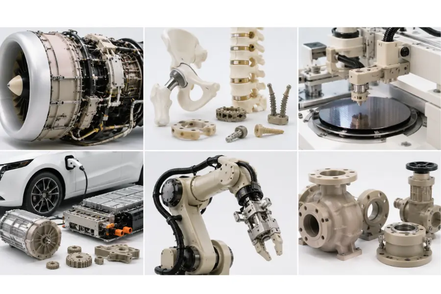
PEEK is rarely specified simply because it has superior material properties. Instead, engineers choose PEEK when conventional plastics cannot reliably withstand the combined effects of heat, chemicals, mechanical loading, wear, and dimensional requirements.
Across different industries, the underlying engineering challenge is remarkably similar: maintaining predictable performance under demanding operating conditions.
Weight reduction remains one of the most important objectives in aerospace engineering.
Replacing selected aluminum or steel components with PEEK allows engineers to reduce mass while maintaining excellent thermal and mechanical performance.
Typical aerospace applications include:
In addition to reducing weight, PEEK offers excellent flame resistance, low smoke generation, and long-term dimensional stability during repeated thermal cycling.
These characteristics help improve reliability while reducing maintenance requirements over extended service intervals.
Modern automotive systems expose components to continuous vibration, elevated temperatures, lubricants, fuels, and aggressive thermal cycling.
PEEK is increasingly used in:
For electric vehicles, reducing component weight contributes directly to improved driving range and energy efficiency.
At the same time, PEEK’s excellent electrical insulation and thermal stability support the increasing power density of modern battery and power electronic systems.
Medical engineering is one of the fastest-growing markets for PEEK.
Unlike metallic implants, PEEK combines structural performance with imaging compatibility and biological safety.
Its engineering advantages include:
These characteristics reduce the likelihood of stress shielding, allowing surrounding bone tissue to continue experiencing physiological loading.
Typical medical applications include:
However, engineers should recognize that implant performance depends not only on material selection but also on implant geometry, surface engineering, sterilization validation, and regulatory compliance.
Semiconductor fabrication demands materials capable of maintaining dimensional precision while minimizing contamination.
PEEK is widely used in:
Its low moisture absorption, excellent chemical resistance, and low particle generation help improve manufacturing yield while reducing contamination risk.
Industrial processing equipment frequently combines elevated temperatures with aggressive chemicals and continuous mechanical operation.
PEEK is commonly specified for:
Because PEEK resists hydrolysis even under prolonged exposure to hot water and steam, it is widely used in pharmaceutical production, food processing, and chemical manufacturing equipment.
Advanced robotics, automation systems, and next-generation mobility platforms increasingly demand lightweight materials with excellent fatigue resistance and dimensional stability.
PEEK is now appearing in applications such as:
Reducing moving mass improves positioning accuracy while lowering energy consumption and extending actuator service life.
Across all of these industries, the decision to specify PEEK follows a common engineering principle.
Rather than optimizing a single property, PEEK enables engineers to simultaneously satisfy requirements for high-temperature performance, wear resistance, chemical stability, lightweight construction, and long-term dimensional accuracy.
Although the initial material and manufacturing costs are higher than those of conventional engineering plastics, the resulting improvements in reliability, maintenance intervals, equipment uptime, and lifecycle performance often justify the investment for critical applications.
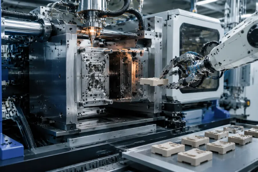
Injection molding is the preferred manufacturing process for producing high-volume PEEK components because it offers excellent repeatability, dimensional consistency, and low unit cost once tooling has been validated. However, molding PEEK is considerably more demanding than processing conventional engineering plastics such as ABS, PC, or PA. Its high melting temperature, relatively high melt viscosity, and semi-crystalline behavior create a much narrower processing window, meaning small variations in temperature, pressure, or cooling can significantly affect final part performance.
Unlike commodity plastics, where the molding process primarily determines part shape, the injection molding process for PEEK also influences crystallinity, mechanical properties, dimensional stability, chemical resistance, and long-term service life. As a result, successful production depends on treating material preparation, mold design, and process optimization as an integrated engineering system rather than independent variables.
Although PEEK exhibits extremely low moisture absorption during service, resin pellets can absorb enough atmospheric moisture during storage to affect melt quality.
Before molding, the material should be thoroughly dried to eliminate residual moisture and maintain stable molecular weight during processing.
| Drying Parameter | Typical Recommendation | Engineering Purpose |
|---|---|---|
| Drying Temperature | 150°C | Removes absorbed moisture |
| Drying Time | Minimum 3 hours | Ensures uniform drying |
| Recommended Moisture Content | Below 0.02% | Minimizes hydrolysis and cosmetic defects |
Insufficient drying commonly results in:
For aerospace, semiconductor, and medical applications, moisture verification is often incorporated into incoming material inspection to improve process consistency before production begins.
Compared with standard engineering plastics, PEEK requires substantially higher processing temperatures throughout the molding cycle.
The following values are commonly used as initial process-development guidelines.
| Processing Parameter | Typical Range |
|---|---|
| Barrel Temperature | 360–400°C |
| Nozzle Temperature | 370–395°C |
| Mold Temperature | 160–200°C |
| Injection Pressure | High (part dependent) |
| Injection Speed | Medium to High |
| Holding Pressure | Optimized according to wall thickness |
| Back Pressure | Moderate for homogeneous melt preparation |
| Drying Temperature | 150°C |
| Drying Time | ≥3 hours |
These values should not be considered universal settings. Actual processing parameters depend on part geometry, wall thickness, gate design, fiber reinforcement, machine capability, and mold construction.
Experienced process engineers generally optimize the entire processing window rather than relying on higher injection pressure alone to solve filling problems.
For semi-crystalline polymers such as PEEK, mold temperature is one of the most influential process variables.
Unlike amorphous plastics, which solidify with relatively consistent structures, PEEK continues developing crystalline regions during cooling. The degree of crystallinity directly influences the finished component’s mechanical and dimensional performance.
Proper mold temperature contributes to:
If mold temperature is too low, crystallization may be incomplete before ejection.
The resulting component may exhibit:
Conversely, excessively high mold temperatures may unnecessarily increase cycle time without providing significant additional performance benefits.
For production environments, maintaining stable mold temperature throughout the entire production run is generally more important than simply maximizing productivity.
Good part design simplifies molding, improves dimensional consistency, and reduces long-term manufacturing costs.
The following recommendations provide practical DFM guidance for injection-molded PEEK components.
| Design Item | Typical Recommendation | Engineering Benefit |
|---|---|---|
| Wall Thickness | Prefer uniform sections between 1–4 mm where practical | Reduces differential shrinkage and sink marks |
| Rib Thickness | Approximately 50–60% of adjacent wall thickness | Improves stiffness without increasing sink risk |
| Gate Thickness | Approximately 50–70% of wall thickness (typically ≥1 mm) | Improves filling of high-viscosity melt |
| Draft Angle | 1–2° depending on geometry | Improves part ejection and reduces mold wear |
| Corner Radius | ≥0.5 × wall thickness | Reduces stress concentration and improves flow |
| Mold Steel | High-temperature tool steel | Supports continuous operation at elevated mold temperatures |
| Venting | Vent near end-of-fill locations | Prevents trapped gas and burn defects |
| Shrinkage Allowance | Approximately 1% (grade dependent) | Improves dimensional accuracy after molding |
These values serve as engineering guidelines and should be validated through simulation, prototype trials, and production sampling.
Many production problems originate during the design stage rather than on the molding machine.
Typical examples include:
Large wall thickness variations
Non-uniform sections cool at different rates, creating differential crystallization, uneven shrinkage, sink marks, and warpage.
Sharp internal corners
Sharp corners increase local stress concentration while also restricting polymer flow during cavity filling.
Adding generous radii generally improves both structural performance and manufacturability.
Undersized gates
Because molten PEEK exhibits relatively high viscosity, small gates increase pressure loss and may cause incomplete filling or poor packing.
Long unsupported flow paths
As flow length increases, pressure requirements rise significantly. Poor gate placement can therefore increase weld lines and dimensional variation.
Conducting a DFM review before mold manufacturing often prevents expensive tooling modifications later in the project.
Injection molding defects should be analyzed by understanding why they occur rather than simply adjusting machine parameters.
The following table summarizes both the visible defect and its underlying engineering mechanism.
| Defect | Failure Mechanism | Engineering Solution |
|---|---|---|
| Short Shot | Melt viscosity exceeds available filling pressure before cavity completion | Increase mold temperature, enlarge gate, shorten flow length |
| Weld Line | Flow fronts cool before sufficient molecular entanglement occurs | Optimize gate location, improve venting, increase melt and mold temperatures |
| Sink Mark | Core material continues shrinking after surface solidification | Improve packing profile and reduce excessive wall thickness |
| Internal Void | Surface freezes before internal material is fully packed | Increase holding pressure and optimize gate efficiency |
| Warpage | Differential crystallization and uneven cooling create residual stress | Balance cooling channels and maintain uniform mold temperature |
| Burn Mark | Trapped gases compress rapidly during filling | Improve vent design and optimize injection speed |
| Flash | Excessive cavity pressure or inadequate mold clamping | Optimize packing pressure and inspect mold condition |
Understanding the material behavior behind each defect generally leads to more stable production than relying solely on parameter adjustments.
For industries such as aerospace, medical devices, and semiconductor manufacturing, producing acceptable parts is only the first step.
Stable production requires validation that the process can consistently manufacture components within specification.
Typical validation activities include:
Rather than relying on visual inspection alone, manufacturers typically validate both product quality and process stability before releasing tooling for mass production.
PEEK components are commonly manufactured using either injection molding or CNC machining. Neither method is universally superior; the appropriate process depends on production volume, development stage, geometry, tolerance requirements, and project economics.
| Selection Factor | Injection Molding | CNC Machining |
|---|---|---|
| Initial Tooling Cost | High | Low |
| Unit Cost | Lowest at high volume | Higher per component |
| Prototype Development | Less suitable | Excellent |
| Design Changes | Costly after tooling | Easy to implement |
| Material Waste | Low | Higher |
| Dimensional Repeatability | Excellent after process validation | Excellent for low-volume production |
| Complex Internal Features | Excellent | Limited by tool accessibility |
| Production Volume | Medium to High | Prototype and Low Volume |
Many successful product development programs follow a staged manufacturing strategy.
| Development Stage | Recommended Process | Engineering Objective |
|---|---|---|
| Concept Prototype | CNC Machining | Rapid functional evaluation |
| Engineering Prototype | CNC Machining | Verify dimensions and assembly |
| DFM Optimization | Moldflow Analysis + Design Review | Reduce manufacturing risk before tooling |
| Tool Sampling (T0/T1) | Injection Molding | Validate mold performance and processing window |
| Pilot Production | Injection Molding | Establish stable production parameters |
| Mass Production | Injection Molding | Maximize repeatability and reduce unit cost |
This progressive approach minimizes development risk while reducing expensive tooling modifications during later production stages.
Like every engineering material, PEEK delivers exceptional performance but also introduces manufacturing and economic trade-offs.
| Advantages | Engineering Trade-offs |
|---|---|
| Continuous service temperatures approaching 250°C | Premium material cost |
| Excellent wear and fatigue resistance | High processing temperatures |
| Outstanding chemical and hydrolysis resistance | Narrow molding process window |
| High strength-to-weight ratio | Specialized equipment required |
| Excellent dimensional stability | Longer cycle times than commodity plastics |
| Natural UL94 V-0 flame resistance | Reinforced grades increase machining and mold wear |
| Excellent biocompatibility | Material selection requires careful cost justification |
From an engineering perspective, the question is rarely “Is PEEK expensive?”
A more useful question is:
“Will PEEK reduce total lifecycle cost?”
| Application Scenario | Is PEEK Justified? | Engineering Reason |
|---|---|---|
| Continuous operation above 200°C | ✔ Yes | Long-term thermal stability |
| Repeated steam sterilization | ✔ Yes | Excellent hydrolysis resistance |
| Semiconductor manufacturing | ✔ Yes | Dimensional stability and low contamination |
| Aerospace lightweight components | ✔ Yes | High strength-to-weight ratio |
| General consumer products | ✘ Usually No | Lower-cost engineering plastics are sufficient |
| Moderate industrial temperatures | ✘ Often No | PPS, PEI, or reinforced PA may provide comparable performance |
For high-value industrial equipment, reducing maintenance, extending service life, or preventing unexpected failures often delivers greater economic value than reducing initial material cost alone. This is why PEEK is frequently selected for mission-critical applications despite its premium price.
Although PEEK is often regarded as the benchmark for high-performance engineering thermoplastics, selecting it simply because it offers the highest specifications is rarely the best engineering approach. Material selection should always balance performance requirements, manufacturing capability, lifecycle cost, regulatory compliance, and long-term reliability.
Experienced design engineers typically begin with the application’s operating conditions rather than the material itself. Questions such as “What temperature will the component experience?”, “Will it operate under continuous sliding wear?”, or “Does it require repeated sterilization?” are generally more valuable than simply comparing tensile strength or melting temperature.
The following comparison illustrates where PEEK fits among commonly used engineering materials.
| Material | Continuous Service Temperature | Wear Resistance | Chemical Resistance | Relative Cost | Typical Applications |
|---|---|---|---|---|---|
| PEEK | Up to 250°C | Excellent | Excellent | Very High | Aerospace, medical, semiconductor, high-performance industrial equipment |
| PEI (Ultem®) | Up to 170–180°C | Good | Good | High | Electrical insulation, aerospace interiors, medical housings |
| PPS | Up to 220°C | Good | Excellent | Medium-High | Pumps, valves, automotive systems |
| PTFE | Up to 260°C | Excellent | Outstanding | High | Bearings, seals, chemical processing |
| Nylon (PA) | Up to 120–150°C | Good | Moderate | Low | Gears, bearings, industrial machinery |
| POM (Acetal) | Up to 100–120°C | Excellent | Good | Low | Precision mechanical components |
| Aluminum | Above 300°C | Moderate | Good | Medium | Structural components and housings |
This comparison demonstrates that PEEK is not intended to replace every engineering plastic or metal. Instead, it occupies a specialized position where several demanding performance requirements must be satisfied simultaneously.
PEEK becomes an excellent engineering solution when a component must withstand multiple severe operating conditions throughout its service life.
Typical examples include:
In these situations, the higher material and manufacturing costs are often offset by longer service life, improved equipment uptime, and reduced maintenance.
PEEK is not always the most economical engineering solution.
Alternative materials may provide a better balance of cost and performance when:
For example, PPS often provides sufficient chemical resistance for pump components at a significantly lower cost, while PEI offers excellent dimensional stability for electrical applications without requiring the high molding temperatures associated with PEEK.
Good engineering is not about selecting the most expensive material—it is about selecting the material that best satisfies the application’s performance requirements with the lowest overall manufacturing and operational risk.
Material selection alone does not guarantee a successful product. Many production issues attributed to PEEK actually originate from poor product design, inadequate manufacturability reviews, or insufficient process validation.
Successful PEEK projects typically begin with Design for Manufacturability (DFM) and continue through structured validation before production release.
The following recommendations summarize common engineering best practices.
| Design Item | Recommended Practice | Engineering Benefit |
|---|---|---|
| Material Grade | Select according to operating temperature, wear, load, and regulatory requirements | Avoids unnecessary material cost and overdesign |
| Wall Thickness | Maintain uniform sections whenever possible | Reduces sink marks, warpage, and differential shrinkage |
| Corner Radius | Radius ≥0.5 × wall thickness | Reduces stress concentration and improves melt flow |
| Draft Angle | Typically 1–2° | Improves demolding and extends mold life |
| Gate Design | Size appropriately for high-viscosity PEEK melt | Improves cavity filling and packing efficiency |
| Cooling Layout | Balance cooling channels throughout the mold | Improves dimensional consistency |
| Shrinkage Compensation | Account for approximately 1% shrinkage (grade dependent) | Improves dimensional accuracy |
| Validation | Verify process capability before production release | Ensures consistent manufacturing quality |
Many molding problems can be eliminated before tooling begins.
The following issues frequently increase production costs.
Large wall thickness variations
Uneven wall sections cool at different rates, resulting in differential crystallization, sink marks, voids, and warpage. Uniform wall thickness generally produces more predictable shrinkage and shorter cycle times.
Sharp internal corners
Sharp corners create localized stress concentrations while restricting melt flow into surrounding regions. Adding generous radii improves both structural integrity and mold filling.
Undersized gates
Because PEEK exhibits relatively high melt viscosity, small gates significantly increase pressure loss. Poor gate sizing often contributes to short shots, inadequate packing, and inconsistent dimensional accuracy.
Ignoring thermal expansion during assembly
Although PEEK has excellent dimensional stability, engineers should still evaluate differences in thermal expansion when assembling PEEK with aluminum, stainless steel, or other engineering materials, particularly in precision mechanical systems.
Experienced manufacturers typically validate both the product and the manufacturing process before approving production tooling.
A typical validation workflow includes:
| Validation Stage | Primary Objective |
|---|---|
| Material Certification | Confirm resin grade and traceability |
| Incoming Material Inspection | Verify moisture level and material condition |
| DFM Review | Identify manufacturing risks before tooling |
| Moldflow Analysis | Predict filling, pressure distribution, and weld line locations |
| T0/T1 Tool Trials | Optimize molding parameters and verify tooling |
| First Article Inspection (FAI) | Confirm dimensional compliance |
| Process Capability Study (Cp/Cpk) | Verify production consistency |
| Production Approval | Release process for mass production |
Although the exact validation sequence varies by industry, this structured approach helps reduce quality variation and lowers production risk during scale-up.
The following matrix provides a simplified starting point when evaluating whether PEEK is the appropriate engineering material.
| If your priority is… | Recommended Solution |
|---|---|
| Maximum operating temperature | PEEK |
| Lowest friction and longest wear life | Bearing-grade PEEK |
| High structural rigidity | Carbon-filled or glass-filled PEEK |
| Medical implant | Virgin medical-grade PEEK with validated surface treatment where required |
| Steam sterilization | Medical-grade PEEK |
| Semiconductor equipment | Virgin high-purity PEEK |
| Lowest material cost | Evaluate PPS, PEI, reinforced PA, or POM before specifying PEEK |
This decision-oriented approach often provides greater value during early product development than comparing individual material properties in isolation.
PEEK is widely used in aerospace, medical devices, semiconductor manufacturing, automotive systems, industrial machinery, and chemical processing equipment. Typical applications include bearings, gears, seals, pump components, electrical insulators, spinal implants, compressor rings, and structural parts operating in high-temperature or chemically aggressive environments.
Yes, in many applications. PEEK offers an excellent strength-to-weight ratio, outstanding corrosion resistance, and electrical insulation, allowing it to replace aluminum, stainless steel, or titanium in selected components. However, highly loaded structural applications may still require metallic materials depending on stiffness, fatigue life, and safety requirements.
Yes. Injection molding is the preferred manufacturing process for medium- and high-volume PEEK components. However, successful molding requires high processing temperatures, careful moisture control, optimized mold temperature, and stable process validation to achieve consistent crystallinity and dimensional accuracy.
PEEK’s high cost results from its complex polymer synthesis, relatively low production volume, demanding processing conditions, and specialized manufacturing equipment. Nevertheless, for mission-critical applications, the improved durability, reduced maintenance, and extended service life often justify the higher initial investment.
The primary limitations of PEEK include premium material cost, high processing temperatures, a relatively narrow molding window, specialized tooling requirements, and sensitivity to concentrated sulfuric acid. Reinforced grades may also increase machining difficulty and accelerate mold and cutting tool wear.
Grade selection depends on the application’s dominant performance requirement. Virgin PEEK provides excellent toughness and purity, glass-filled grades improve dimensional stability, carbon-filled grades enhance wear resistance and stiffness, and bearing-grade PEEK minimizes friction during continuous sliding contact. The final selection should consider operating temperature, loading conditions, wear mechanisms, regulatory requirements, and manufacturing capability.
PEEK has established itself as one of the world’s most capable engineering thermoplastics because it combines exceptional thermal stability, mechanical strength, chemical resistance, wear performance, and dimensional accuracy within a single material system. These characteristics enable engineers to solve design challenges that conventional engineering plastics—and in some cases metals—cannot address effectively.
However, specifying PEEK should never be viewed as a default material upgrade. Its premium cost and demanding processing requirements require careful evaluation of operating temperature, mechanical loading, production volume, manufacturing capability, validation requirements, and total lifecycle cost. In many moderate-duty applications, materials such as PPS, PEI, or reinforced engineering polyamides may provide a more economical solution.
For applications operating in extreme thermal, mechanical, or chemical environments, however, PEEK often delivers outstanding long-term value. By selecting the appropriate grade, incorporating sound DFM principles, validating the manufacturing process, and considering engineering trade-offs throughout product development, manufacturers can fully leverage PEEK’s performance while achieving consistent production quality, reduced operational risk, and lower total ownership cost over the component’s lifecycle.